Boom breakaway system

a boom and breakaway technology, applied in the field of agricultural booms, can solve the problems of catastrophic damage to the wing structure of the sprayer, unusable sprayer, costly and time-consuming wing repair, etc., and achieve the effect of limiting the overall boom load, preventing excess boom momentum and oscillation, and limiting the impact load through the boom

Active Publication Date: 2005-08-25
DEERE & CO
View PDF13 Cites 21 Cited by
  • Summary
  • Abstract
  • Description
  • Claims
  • Application Information

AI Technical Summary

Benefits of technology

[0004] It is yet another object of the present invention to provide an improved boom breakaway system which can absorb sufficient impact force to limit overall boom loading to non-destructive levels while at the same time preventing excess boom momentum and oscillation.
[0005] It is another object of the present invention to provide an improved breakaway system for a boom which is particularly useful for use with the large multi-section booms. It is yet another object to provide such a system which provides inner boom section pivoting relative to a center frame. It is a further object to provide such a system which provides a relatively large and controlled boom travel to clear an obstacle.
[0006] It is a further object to provide an improved hydraulically operated boom breakaway system. It is another object to provide such a system having a staged pressure buildup during breakaway which effectively absorbs impact energy hydraulically before a breakaway cylinder reaches full stroke. It is a further object to provide such a system which operates smoothly and effectively limits impact loads through the boom to reduce or eliminate structural damage during an impact.
[0007] Boom inner wings are attached to a boom center frame at hinge joints which normally allow the wings to fold 90 degrees from a forward transport position to an extended spraying position under the control of a hydraulic folding cylinder. In the present design, the fold cylinder, which in many previous designs extended between the center frame and inner wing, is attached to a rocker that is pivotally connected to the center frame. The rocker is attached to a breakaway hydraulic cylinder normally pressurize...

Problems solved by technology

The sprayer boom wing structure can experience catastrophic damage rendering the sprayer unusable if the boom impacts an immovable object such as a telephone pole.
The damage results in a costly and time-consuming wing repair.
Some presently available hydraulic systems include a complex and expensive cylinder with built-in cushion...

Method used


Image

  • Boom breakaway system
  • Boom breakaway system
  • Boom breakaway system

Examples


Embodiment Construction

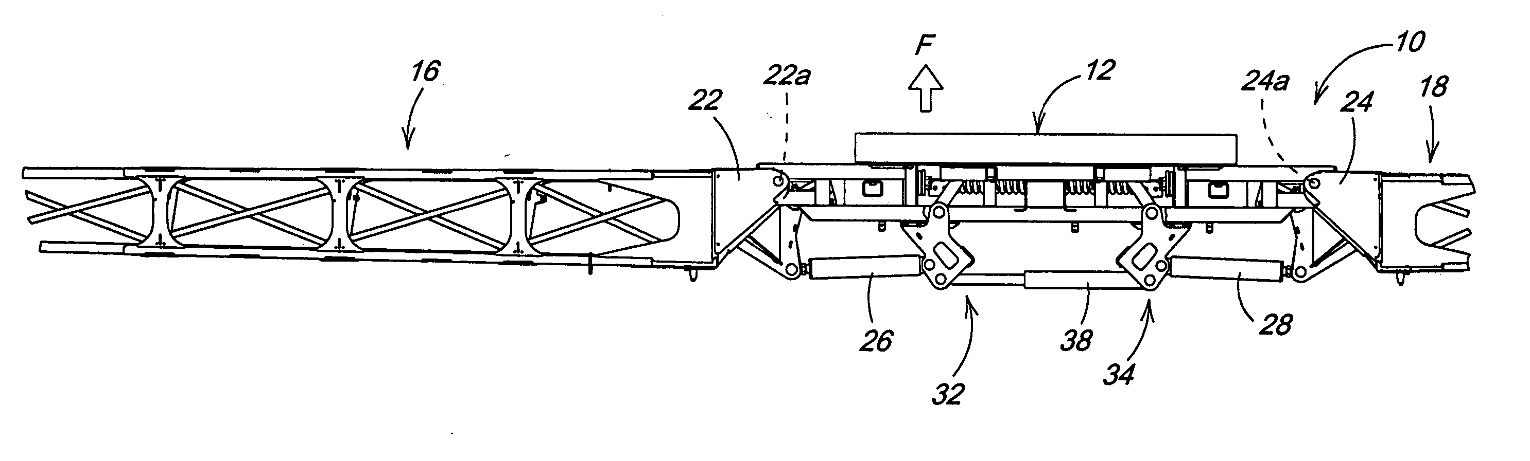
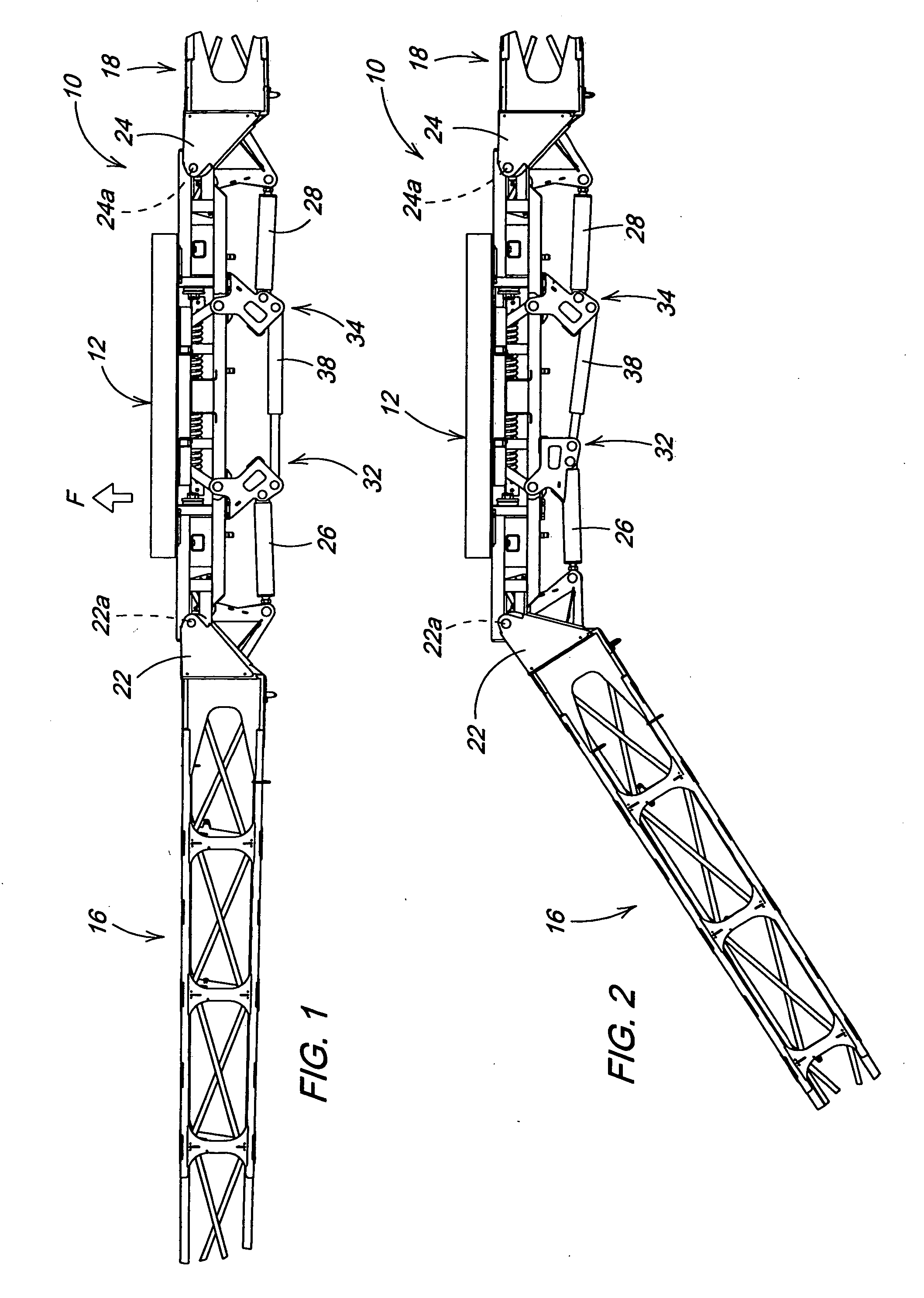
[0017] Referring now to FIGS. 1 and 2, therein is shown a portion of an implement 10 having a cushioned center frame 12 carried on a vehicle frame (not shown) such as a self-propelled vehicle or towed trailer adapted for forward movement F over a field. Folding left-hand and right-hand inner boom sections 16 and 18 are connected by hinge structure 22 and 24, respectively, to opposite sides of the center frame 12 for pivoting about upright axes 22a and 24a between an outwardly directed field-working position (FIG. 1) and a forwardly folded transport position (not shown) by fold cylinders 26 and 28. Additional outer wing sections can be attached to the ends of the boom sections 16 and 18 to provide a working width of up to 120 feet or more.

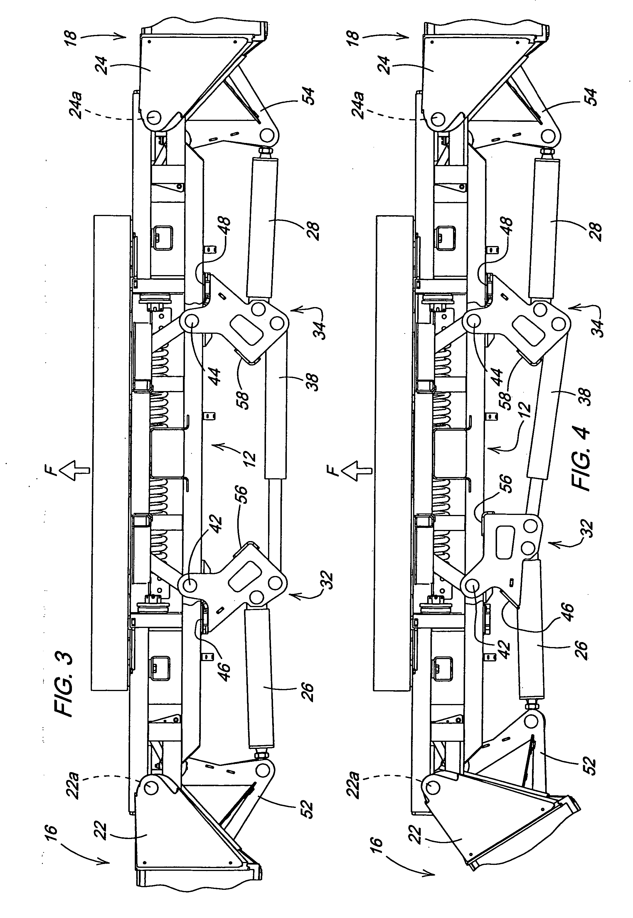
[0018] The fold cylinders 26 and 28 are connected to rocker structures indicated generally at 32 and 34. The rocker structures are pivotally connected to the center frame 12 and to ends of the fold cylinders 26 and 28. A breakaway cylinder 38 is co...


PUM


Abstract

Foldable boom inner wings are attached to a boom center frame through a rocker attached to a breakaway hydraulic cylinder pressurized to full stroke and connected to an accumulator. When a wing impacts an object, the impact load is transmitted through the fold cylinder and rocker into the breakaway cylinder. As the breakaway cylinder retracts to allow the wing to pivot, pressure builds in the system in three stages. First pressure builds along an accumulator pressure curve until a relief valve in the hydraulic system actives to initiate the second stage wherein oil is dumped through the relief valve. Thereafter, pressure is again allowed to build along the same accumulator curve to absorb impact hydraulically before the cylinder reaches full stroke. The staged pressure buildup prevents boom momentum from gaining and loads from increasing above the strength of the overall structure.

Description

FIELD OF THE INVENTION [0001] The present invention relates generally to agricultural booms and, more specifically, to a breakaway boom for a field sprayer or the like. BACKGROUND OF THE INVENTION [0002] The boom of a modern agricultural sprayer typically includes folding wing structure that unfolds to a working width of 90 to 120 feet or more. The sprayer operator can apply chemicals at speeds ranging from 10 to 20 mph, and it is not uncommon for the boom to impact an obstacle in the field during sprayer operation. The sprayer boom wing structure can experience catastrophic damage rendering the sprayer unusable if the boom impacts an immovable object such as a telephone pole. The damage results in a costly and time-consuming wing repair. To reduce or eliminate such impact damage, various boom fold structure linkages have been devised to allow outer wings or the boom wing which is attached to the boom center frame to fold rearward during an impact. The amount of rearward travel must...

Claims


Application Information

Patent Timeline
IPC IPC(8): A01M7/00
CPCA01M7/0078A01M7/0053
Inventor WUBBEN, THOMAS MARKKLEMME, KENT ALVINGAMBLETON, VERNON KENTCARLSON, BRANDON CYBRETT, WILLIAM ANTHONYMILLER, MATTHEW T.
Owner DEERE & CO
Why Eureka
Try Eureka