
Sealing member for enclosures

a technology for sealing members and enclosures, applied in the field of sealing members, can solve the problems of increasing the difficulty of sealing methods, increasing the difficulty of sealing reliable, and the difficulty of using mastic or rubber tape to form seals

Active Publication Date: 2008-10-28
CORNING RES & DEV CORP
View PDF22 Cites 38 Cited by
  • Summary
  • Abstract
  • Description
  • Claims
  • Application Information

AI Technical Summary

Benefits of technology

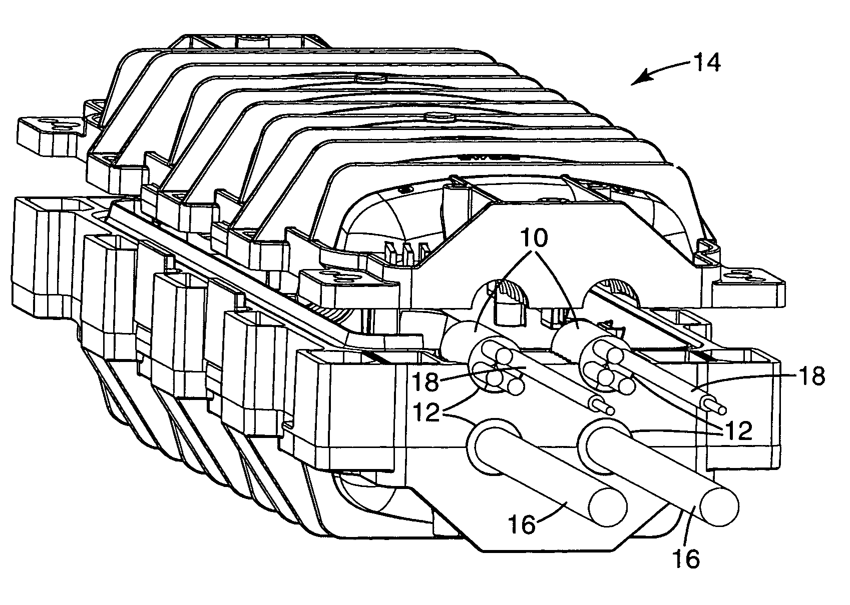
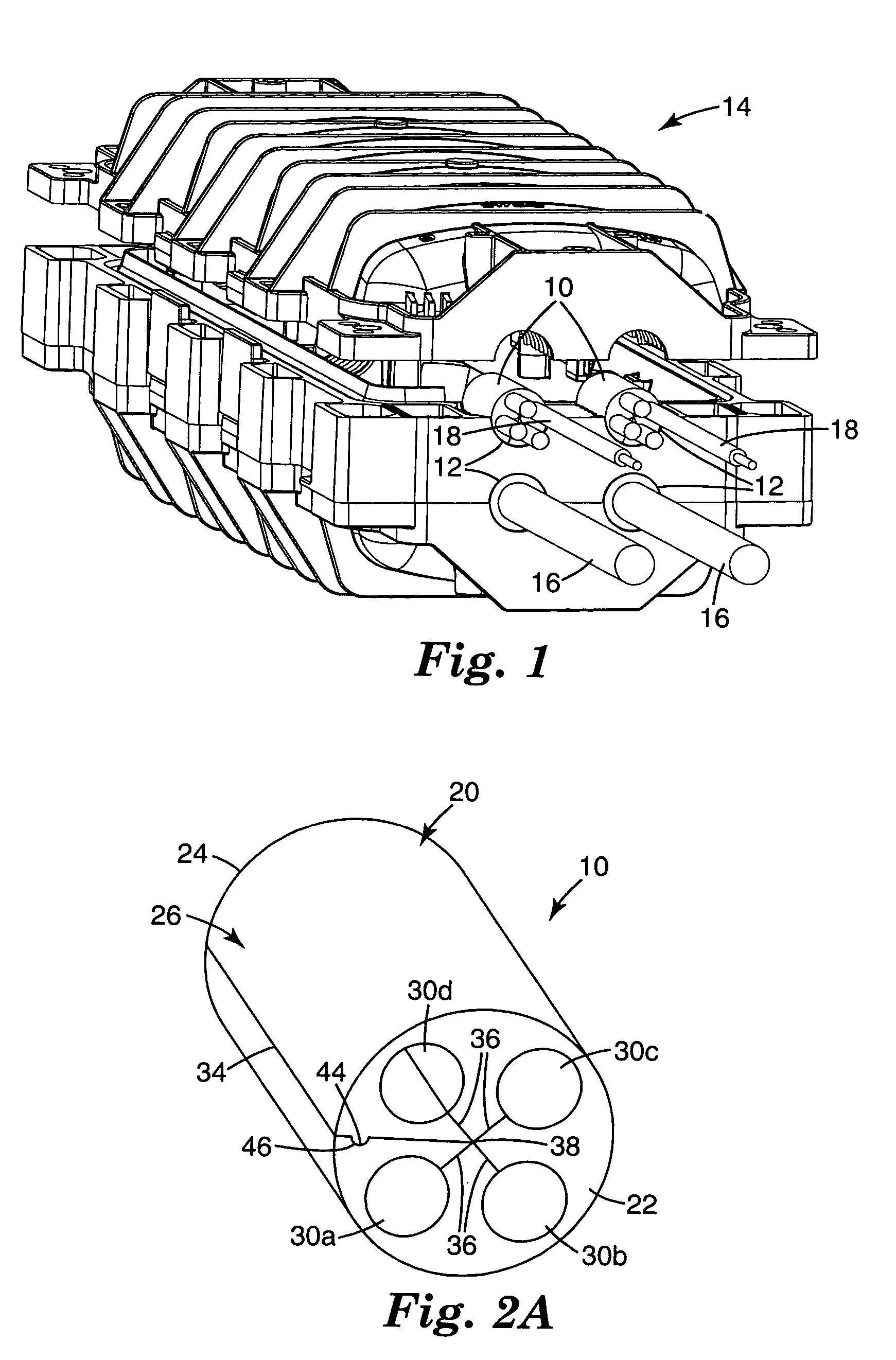
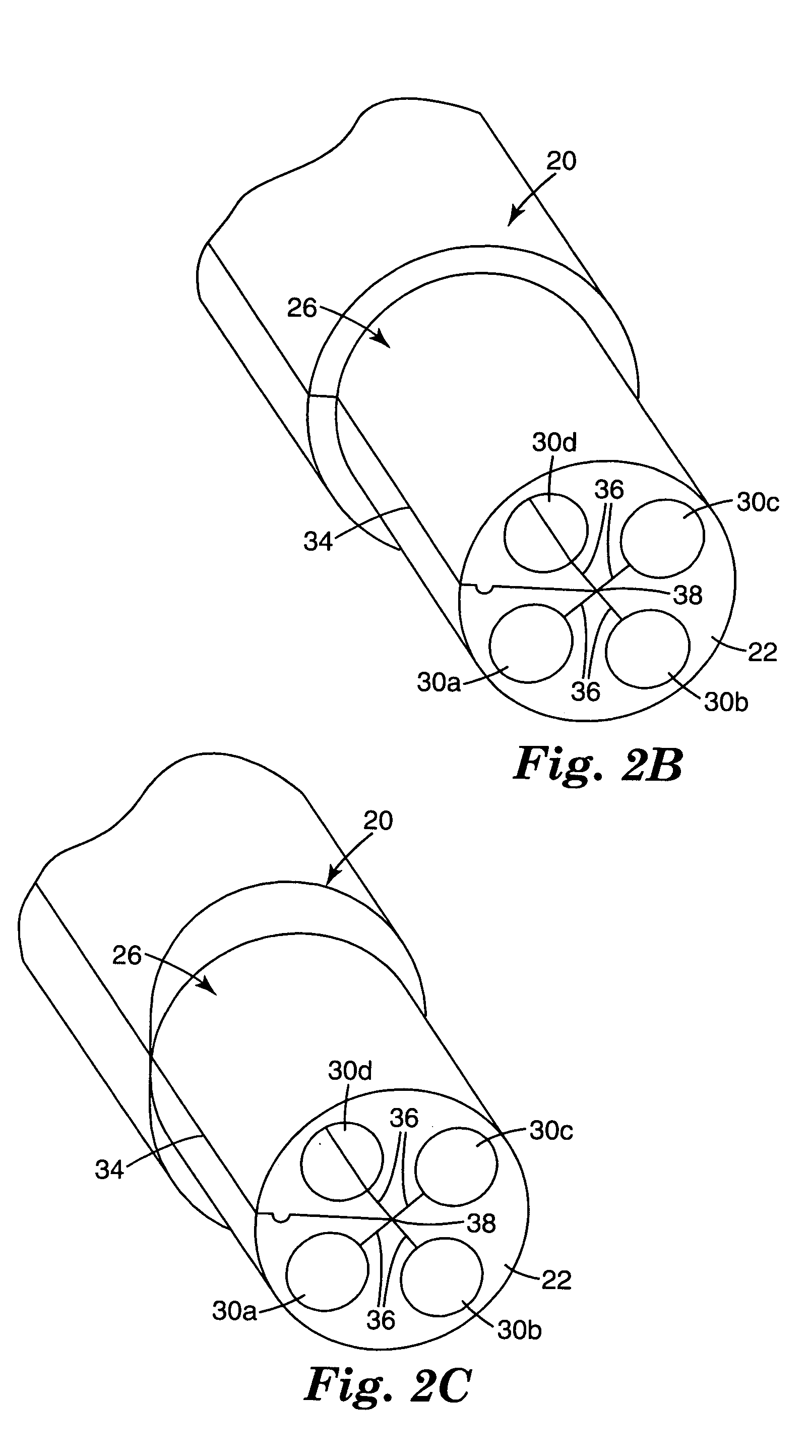
The invention described herein provides a seal for use in an entry port of an enclosure. The seal has a body with a slit that passes through it, and a plurality of passages that can receive components. The seal can be expanded to increase the capacity of the entry port by adding more passages. The invention also provides a kit for sealing components passing through an opening in an enclosure, and a method for preparing a cable for sealing within an opening in an enclosure. The technical effects of the invention include improved sealing for components passing through an opening in an enclosure, increased capacity, and improved preparation of cables for sealing.

Problems solved by technology

Such sealing methods are replete with disadvantages.
The quality of the resulting seal is highly dependent upon the skill of the installer, and is therefore typically inconsistent from one installer to another installer.
Further, as the number of cables increases, it becomes more and more difficult to form a reliable seal.
The use of mastic or rubber tape to form a seal also presents difficulties when it is desired to re-enter the enclosure, so as to add or remove cables in the entry port.
The removal and reconstruction of the seal requires the use of additional time and materials, and therefore adds to the cost of maintaining or expanding the network.
Such grommets have the disadvantage that the cables must have a free end to thread through the grommet openings.
However, in many applications a free cable end is not available because the cable has already been connected, spliced or terminated.
Successfully cutting into the grommet in this manner is very dependent upon the skill of installer, and becomes increasingly difficult as the number of cables increases and as the size of the grommet and cables decreases.
The cuts degrade the reliability of the grommet, and are a potential pathway for the ingress of moisture into the enclosure.

Method used


Image

  • Sealing member for enclosures
  • Sealing member for enclosures
  • Sealing member for enclosures

Examples


Embodiment Construction

[0025]In the following detailed description of the preferred embodiments, reference is made to the accompanying drawings, which form a part hereof, and in which is shown by way of illustration specific embodiments in which the invention may be practiced. The illustrated embodiments are not intended to be exhaustive of all embodiments according to the invention. It is to be understood that other embodiments may be utilized and structural or logical changes may be made without departing from the scope of the present invention. The following detailed description, therefore, is not to be taken in a limiting sense, and the scope of the present invention is defined by the appended claims.

[0026]For purposes of clarity, the invention is described herein as used with cables. However, such use is exemplary only, and the term “cable” as used herein is understood and intended to include any member or component that passes through an opening in an enclosure, including but not limited to telecomm...


PUM


Abstract

A seal includes a body having an exterior surface configured for sealing engagement with an entry port of an enclosure. A plurality of passages extend from a first end of the body to a second end of the body. Each of the plurality of passages is configured to receive at least one component therein. A body slit extends from the first end to the second end, and passes through the body from the exterior surface to an interior point in the body. A plurality of passage slits extend from the first end to the second end. Each of the plurality of passage slits pass through the body from the interior point in the body to a corresponding one of the plurality of passages.

Description

THE FIELD OF THE INVENTION[0001]The present invention generally relates to enclosures having openings for allowing members, such as cables, to pass into the enclosure. More particularly, the present invention relates to a sealing member for use in the openings of such enclosures, the sealing member configured to seal around a plurality of members as they pass through an opening in a wall of the enclosure.BACKGROUND OF THE INVENTION[0002]Cables, such as telecommunication cables and electrical power distribution cables, are ubiquitous and used for distributing electrical power and all manner of data across vast networks. The majority of cables are electrically conductive cables (typically copper), although the use of optical fiber cables is growing rapidly in telecommunication systems as larger and larger amounts of data are transmitted. As cables are routed across power or data networks, it is necessary to periodically open the cable and splice or tap into the cable so that power or ...

Claims


Application Information

Patent Timeline
Patent Type & Authority Patents(United States)
IPC IPC(8): H02G3/18
CPCH02G15/013H02G15/113H02G15/117Y10T16/05Y10T16/063
Inventor BALL, SHIRLEY E.BERGLUND, SIDNEY J.KRENZ, DEAN C.RICKS, RONALD J.
Owner CORNING RES & DEV CORP
Learn More