Cabinet lock

a cabinet and lock technology, applied in the field of cabinet locks and cabinets, can solve the problems of cumbersome or difficult to achieve the way in which the adult can access the cabinet, and the difficulty of obtaining such access, and the difficulty of controlling the access of certain goods or properties

Active Publication Date: 2008-11-04
MAGNA ELECTRONICS INC
View PDF12 Cites 15 Cited by
  • Summary
  • Abstract
  • Description
  • Claims
  • Application Information

AI Technical Summary

Benefits of technology

[0008]a striker including a coupling region with which said bolt can couple to thereby isolate relative movement between said latch bolt and said striker in at least one direction lateral to the direction of movement of said bolt between its locking position and said unlocked position,
[0011]said striker including an interference means movable to interfere with the movement of said bolt into coupling engagement with said coupling region of said striker to thereby prevent coupling.
[0013]Preferably said striker includes an aperture, said coupling of said bolt and said striker occurring by a penetrative engagement of said bolt with said aperture thereby isolating relative movement between said latch bolt and said striker in at least one direction lateral to the direction of penetration of said bolt.
[0042]a striker including a coupling region with which said bolt can couple to thereby isolate relative movement between said latch bolt and said striker in at least one direction lateral to the direction of movement of said bolt between its locking position and said unlocked position,

Problems solved by technology

Access to certain goods or property often needs to be limited or controlled.
However some such kitchen cabinets are in frequent use by adults and it is not desirable for the manner in which access is restricted to the cabinets to be cumbersome or difficult to achieve.
An issue which will arise by having a locking mechanism mounted internally is that access to such may then also be difficult to obtain by an adult who does wish to have access to the interior of the cabinet.
Since in most circumstances the cabinet doors or drawers will be in a closed condition, in such a default condition it would be undesirable for continuous power to be drawn by a locking unit.
Such may be desirable for a significant duration of time and it would be undesirable for the locking device to, during such periods of time, be drawing power from a power source in order to achieve such an unlocked position.

Method used


Image

  • Cabinet lock
  • Cabinet lock
  • Cabinet lock

Examples


Embodiment Construction

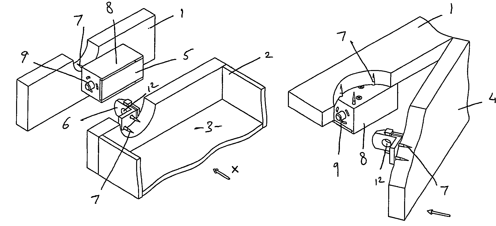
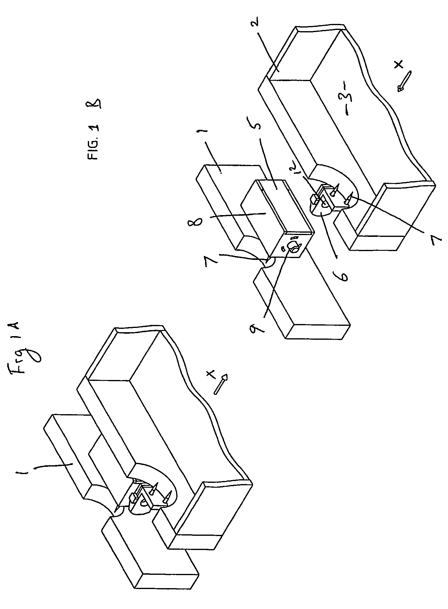
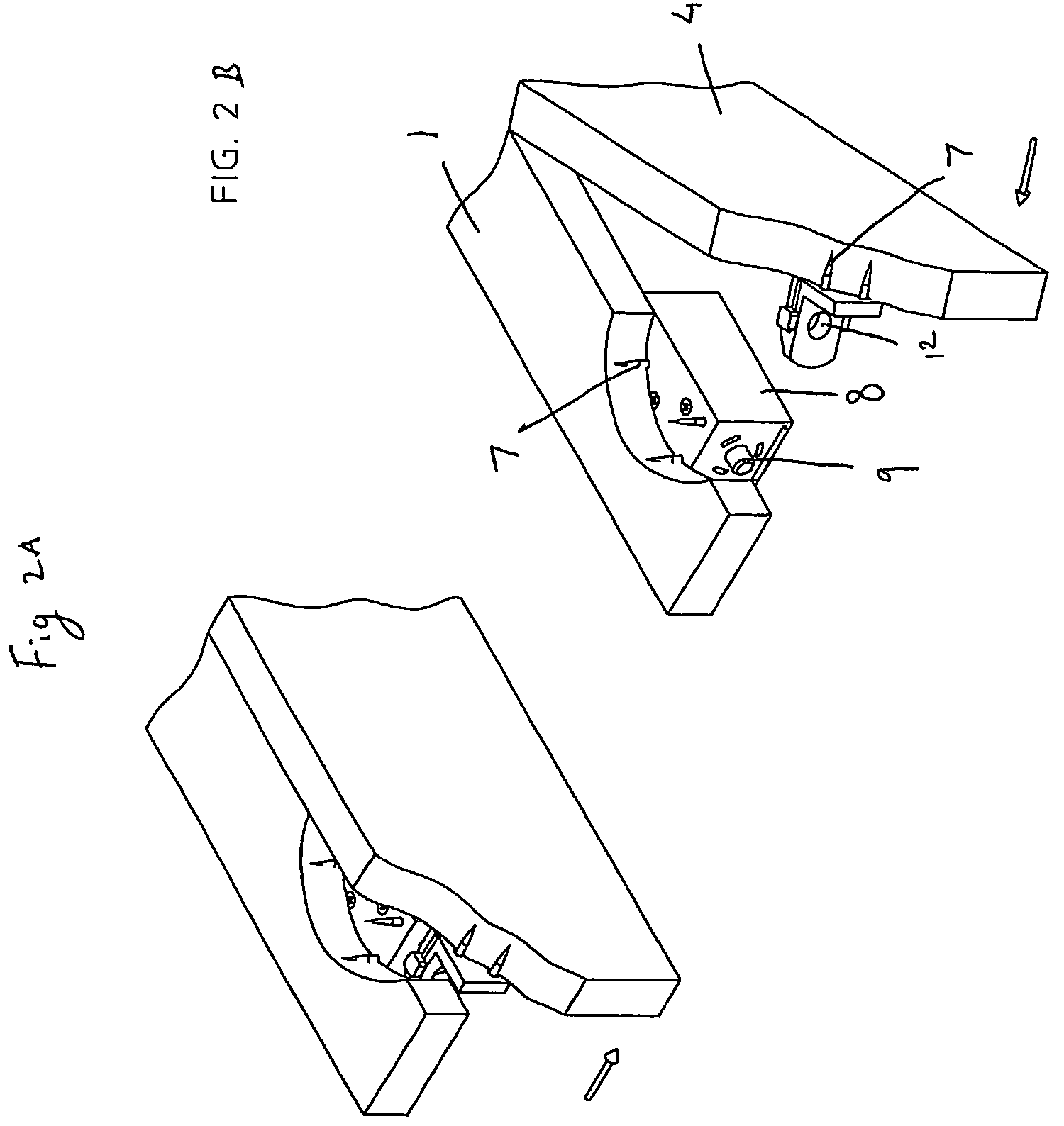
[0068]With reference to FIG. 1B there is shown part of a cabinet which includes a compartment structure 1 and a drawer 2 which is movable relative to the compartment structure in a linear fashion and for example in direction X relative to the compartment structure 1. The compartment structure 1 may include a back wall of the compartment with which part of the cabinet lock is engaged. The drawer 2 can extend and be drawn from the compartment structure 1 to expose the drawer containment region 3 to the exterior of the compartment structure 1. In an alternative application the cabinet lock of the present invention may be utilized where a door 4 is pivotally movable relative to the compartment structure 1 which with reference to FIG. 2B may for example be a shelf or top wall member of the fixed compartment structure. The door 4 will be pivotally dependent to the compartment structure so as to be able to open and close an opening to the compartment structure to thereby allow and prevent ...


PUM


Abstract

A cabinet lock for selectively locking a cabinet of a kind including a compartment structure and a closure movable relative to the compartment structure for selectively closing an opening of the compartment structure. The cabinet lock including a latch bolt assembly including a mounting and a bolt movably disposed with the mounting between a locking position and an unlocked position. Also provided is a striker including a coupling region with which the bolt can couple to thereby isolate relative movement between the latch bolt and the striker in at least one direction lateral to the direction of movement of the bolt between its locking position and the unlocked position. The striker is engagable with the compartment structure and the latch bolt is engagable with the closure in a manner to place such in coupling proximity when the closure is in closing relation with the opening of the compartment structure.

Description

[0001]This is a nationalization of PCT / NZ04 / 000253 filed Oct. 15, 2004 and published in English.FIELD OF THE INVENTION[0002]The present invention relates to a cabinet lock and a cabinet including such a lock which in particular although not solely is provided for the purposes of providing a safety locking system for preventing children or other undesired access to the interior of a cabinet.BACKGROUND OF THE INVENTION[0003]Access to certain goods or property often needs to be limited or controlled. For example in a domestic situation cleaning products or other chemicals are often stored in kitchen cabinets. Where children or toddlers are able to reach such locations it becomes essential for access to the storage regions of the cabinets to be controlled and in most situations to be secured so as to prevent a toddler from gaining access to such locations. However some such kitchen cabinets are in frequent use by adults and it is not desirable for the manner in which access is restricte...

Claims


Application Information

Patent Timeline
Patent Type & Authority Patents(United States)
IPC IPC(8): E05C1/06E05B15/02E05B47/02E05B63/00E05B63/18E05B65/00E05B65/44E05B65/46E05B65/462E05C1/08
CPCE05B15/0205E05B47/026E05B65/0014E05B65/46E05B15/029E05B47/0002E05B63/0065E05B65/44E05B65/462Y10T292/1021Y10T292/694
Inventor NYE-HINGSTON, MATTHEW RICHARD ALEXHINGSTON, NEIL RICHARD
Owner MAGNA ELECTRONICS INC
Why Eureka
Try Eureka