Rearview mirror system for accommodating a rain sensor

a technology for rearview mirrors and rain sensors, applied in the direction of optical radiation measurement, instruments, electric devices, etc., can solve the problems of varying the amount of rain falling on the windshield, relatively expensive processes, and dramatic rainfall rates

Inactive Publication Date: 2008-11-04
GENTEX CORP
View PDF52 Cites 52 Cited by
  • Summary
  • Abstract
  • Description
  • Claims
  • Application Information

AI Technical Summary

Benefits of technology

[0008]In yet another aspect of the present invention, a viewing system for a vehicle having a windshield, a button connected thereto and a sensor being retained against the windshield by a retainer is provided. The viewing system comprises an interior rearview mirror system configured to be connected to the button and be located adjacent the sensor. The interior rearview mirror system includes a mechanism configured to engage the retainer. The interior rearview mirror system does not bias the sensor against the windshield when the interior rearview mirror is connected to the button. Rather, the mechanism is configured to engage the retainer as the interior rearview mirror system is detached from the button to thereby pull the retainer away from the sensor, thereby allowing the sensor to fa

Problems solved by technology

Unfortunately, the rate of rainfall may vary dramatically over a given period of time.
Additionally, traffic conditions may also cause varying amounts of rain to fall on the windshields, such as when a truck passes by.
As a result, during such conditions, the driver must frequently adjust the wiper time interval, whic

Method used


Image

  • Rearview mirror system for accommodating a rain sensor
  • Rearview mirror system for accommodating a rain sensor
  • Rearview mirror system for accommodating a rain sensor

Examples


first embodiment

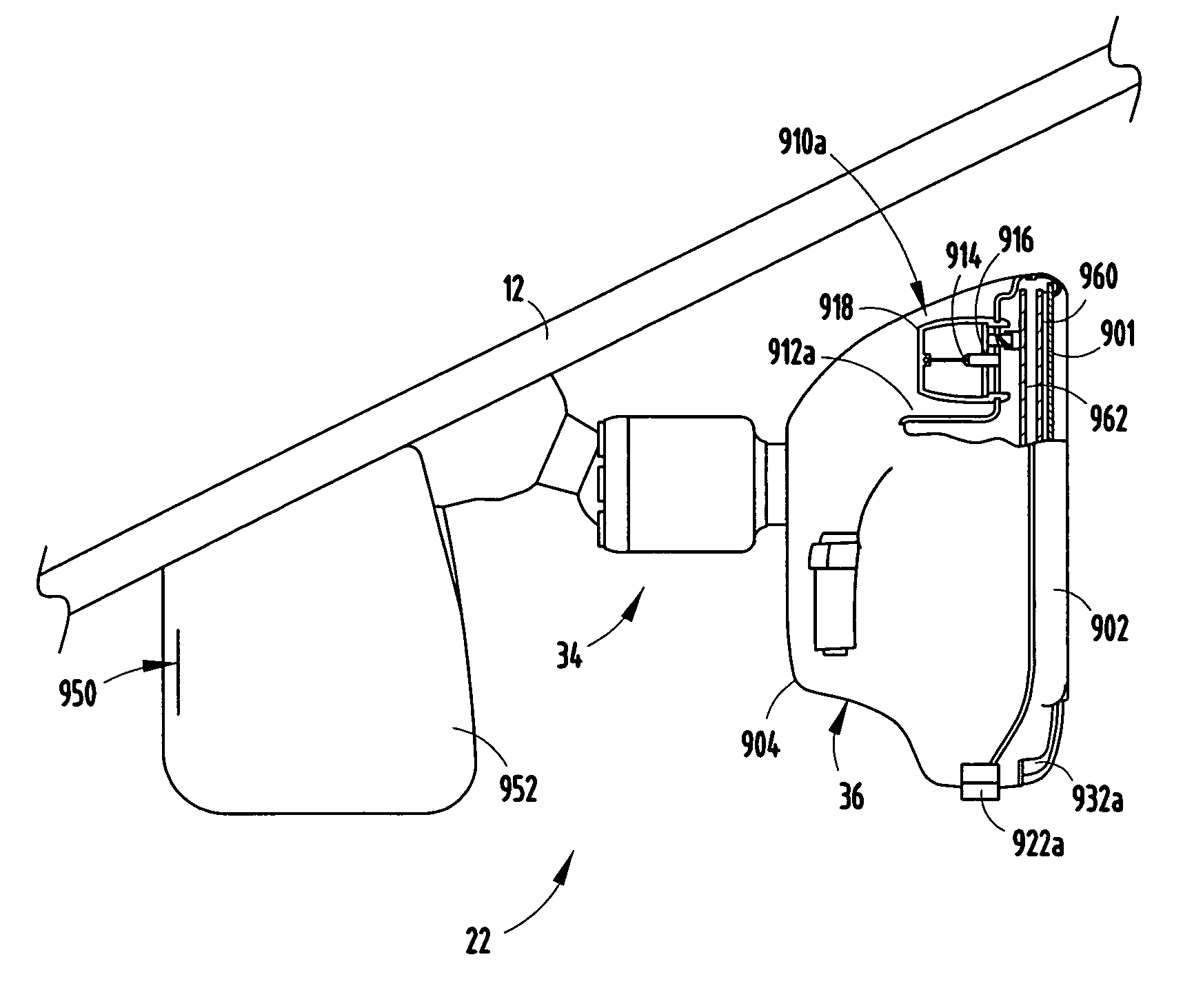
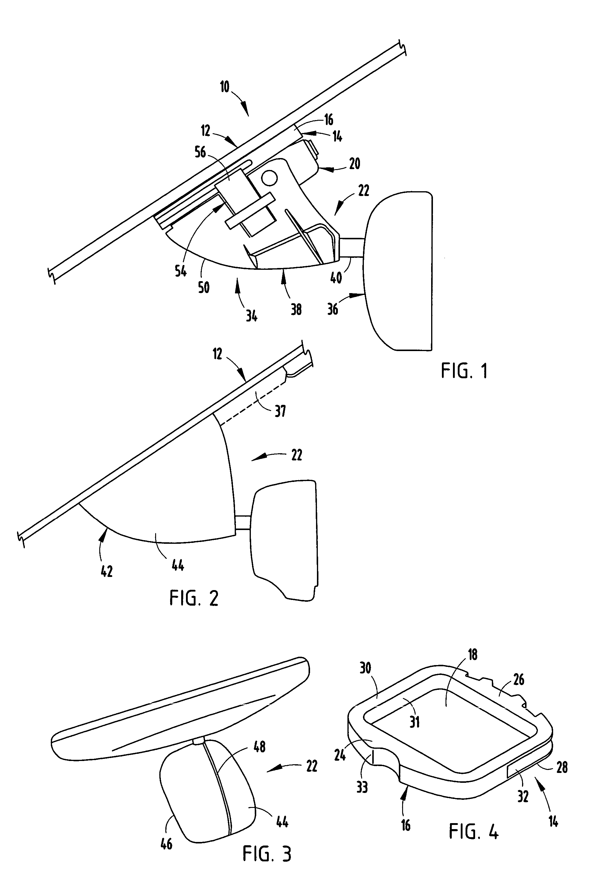
[0063]In the illustrated example, the interior rearview mirror system 22 of the present invention is connected to the button 14 by sliding the mounting foot 38 onto the button 14 as described above. Furthermore, the ribs 66 of the interior rearview mirror system 22 slide below the ledges 61 of the rain sensor 20 to thereby position the ribs 66 and the ledges 63 of the interior rearview mirror system 22 between the windshield 12 and the ledges 61 of the rain sensor 20. Thereafter, the mounting bracket cover 42 is positioned over the mounting bracket 34 of the interior rearview mirror system 22, the button 14 and the rain sensor 20. Preferably, the ledges 63 of the interior rearview mirror system 22 do not contact the ledges 61 of the rain sensor 20 once the interior rearview mirror system 22 is connected to the button 14 and before the interior rearview mirror system 22 is disconnected from the button 14.

[0064]As the illustrated interior rearview mirror system 22 is disconnected from...

second embodiment

[0068]In the illustrated example, the rain sensor 20a is operatively coupled to the windshield 12a independent of the interior rearview mirror system 22a. However, as the interior rearview mirror system 22a is detached from the button 14a, the ledges 63a of the interior rearview mirror system 22a engage the ledges 61a of the rain sensor 20a, thereby disconnecting at least a portion of the rain sensor 20a from the windshield 12a. In the visual, rear viewing and rain sensing system 10a for the vehicle, the ledges 61a of the rain sensor 20a could be located within channels 80 that accept the hooks 78 of the spring clip 70 as the interior rearview mirror system 22a is disconnected from the button 14a.

[0069]The reference numeral 10b (FIGS. 13-15A) generally designates another embodiment of the present invention, having a third embodiment of the visual, rear viewing and rain sensing system for the vehicle. Since visual, rear viewing and rain sensing system 10b is similar to the previousl...

third embodiment

[0070]The illustrated spring clip 70b of the visual, rear viewing and rain sensing system 10b for the vehicle is snap fit into position after the interior rearview mirror system 22b has been connected to the button 14b. The legs 72b, 74b of the spring clip 70b include shelves 82 wherein upper portions of the legs 72b, 74b are spaced further apart than lower portions of the legs 72b, 74b. Furthermore, the sides of the shell 50b of the mounting foot 38b include downward facing notches 84 configured to engage the shelves 82 of the spring clip 70b. After the interior rearview mirror system 22b has been connected to the button 14b, the spring clip 70b is fit over the mounting foot 38b of the mounting bracket 34b. Therefore, the shelves 82 of the spring clip 70b snap into position under the notches 84 of the mounting foot 38b and the hooks 78b of the spring clip 70b snap under the ledges 61b of the rain sensor 20b. Thereafter, the ledges 63b of the spring clip 70b pull at least a portion ...


PUM


Abstract

A visual, rear viewing and rain sensing system for a vehicle comprising a windshield and a button connected to the windshield, with the button having a peripheral body defining an open area in a middle section of the button. The visual, rear viewing and rain sensing system further includes a rain sensor located in the middle section and an interior rearview mirror system connected to the button. The rain sensor is operatively coupled to the windshield independent of the interior rearview mirror system. At least a portion of the rain sensor is no longer operatively coupled to the windshield as the interior rearview mirror system is detached from the button.

Description

CROSS-REFERENCE TO RELATED APPLICATION[0001]This application claims the benefit of U.S. Provisional Application No. 60 / 472,017, filed May 20, 2003.BACKGROUND OF THE INVENTION[0002]The present invention relates to a system for automatically detecting the presence of moisture on a surface, such as the surface of a windshield of a vehicle for an automobile, in order to automatically actuate the vehicle's windshield wipers and / or defroster or defogging system and to safely detach the moisture detectors system as a interior rearview mirror system is detached from the windshield.[0003]In conventional windshield wiper systems, the windshield wipers are actuated based on the elapsed time between wipes rather than the moisture level on the exterior of the windshield.[0004]During conditions of relatively consistent rainfall, for example, the time interval can be adjusted to correspond to the amount of time in which the rain accumulates to the point of the desired visibility level. Unfortunate...

Claims


Application Information

Patent Timeline
IPC IPC(8): H02G3/00B60R1/04B60R1/12
CPCB60R1/04B60R1/12B60R2001/1223
Inventor PARKER, BRIAN R.REES, BRIAN J.RUMSEY, WAYNE J.DEVRIES, TIMOTHY S.CARTER, JOHN W.
Owner GENTEX CORP
Why Eureka
Try Eureka