Lock assembly

a technology of lock assembly and lock body, which is applied in the direction of cylinder locks, building locks, constructions, etc., can solve the problems of time-consuming, troublesome adjustment of the lock assembly of the '242 application, and invariability of traditional lock assembly us

Active Publication Date: 2008-11-11
TAIWAN FU HSING INDAL
View PDF19 Cites 47 Cited by
  • Summary
  • Abstract
  • Description
  • Claims
  • Application Information

AI Technical Summary

Benefits of technology

[0009]The main objective of the invention is to provide a lock assembly that can be adjusted to fit with different keys conveniently and quickly.

Problems solved by technology

A traditional lock assembly is only applied with a specific key and cannot fit with different keys.
To use with different keys, an old lock cylinder should be replaced with a new one, such that the traditional lock assembly is not versatile in use.
However, a specific tool is need for adjusting the lock assembly of the '242 application, and the tool is not an inherent part of the lock assembly.
Therefore, the adjustment of the lock assembly of the '242 application is troublesome and time-consuming.

Method used


Image

  • Lock assembly
  • Lock assembly
  • Lock assembly

Examples


first embodiment

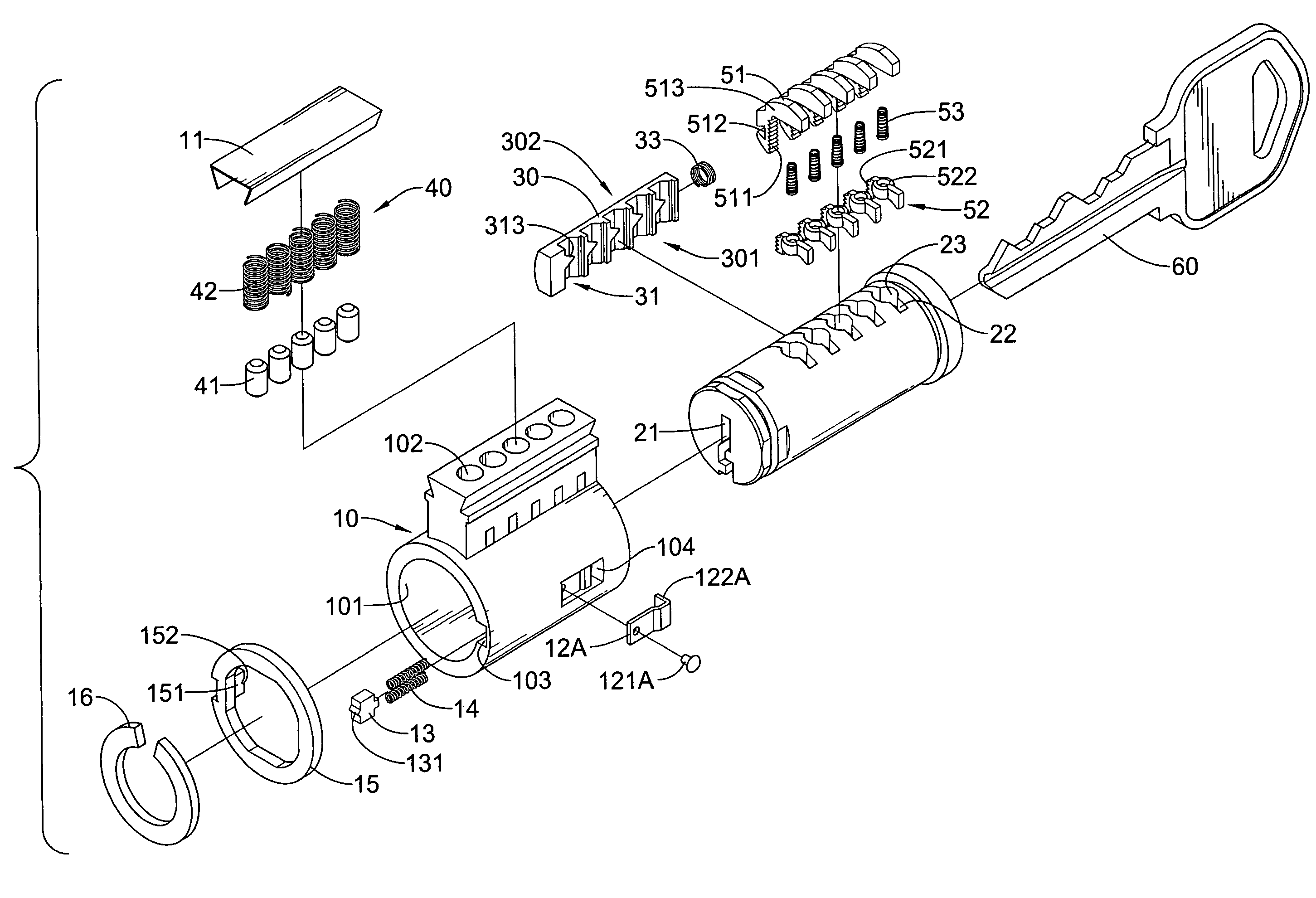
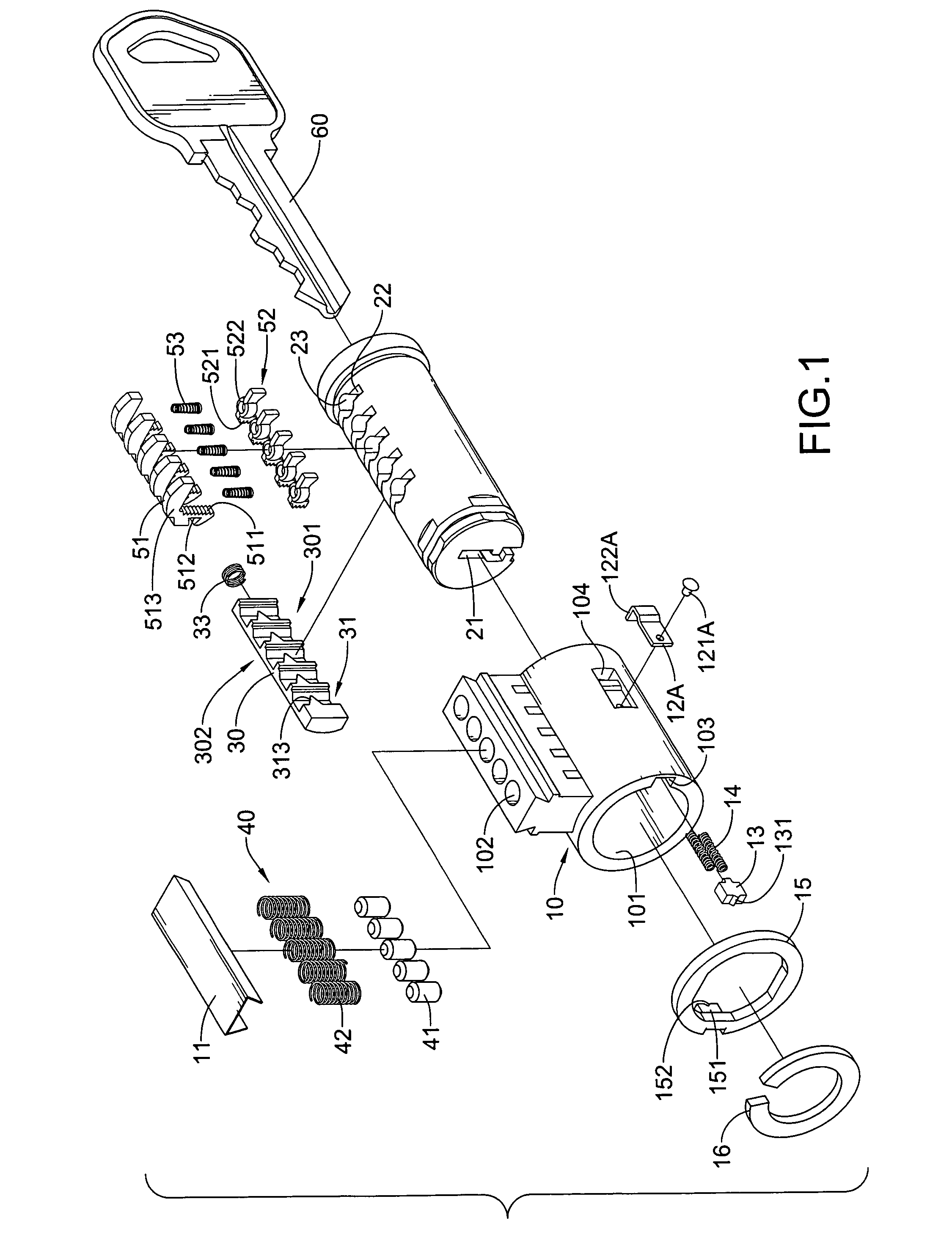
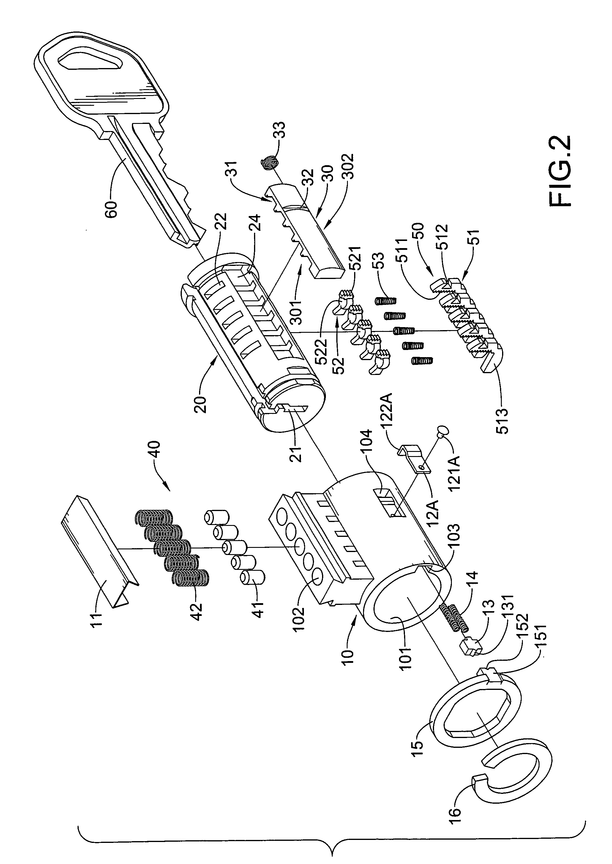
[0029]The positioning element (13) is mounted on and extends from the housing (10). In a first embodiment, an alignment channel (103) is defined in an inner surface of the cylinder hole (101) at a rear end of the housing (10), and the positioning element (13) is slidably mounted in and extends out of the alignment channel (103). At least one spring (14) is mounted in the alignment channel (103) and abuts the positioning element (13) to push the positioning element (13) out of the alignment channel (103). The positioning element (13) may have a positioning tip (131) formed on and protruding from the positioning element (13).

[0030]With reference to FIGS. 5 to 7, in an alternative embodiment, an alignment notch (105) is defined in a rear end of the housing (10A,10B), and the positioning element (13A) is mounted in and extends out of the alignment notch (105) and has a positioning tip (131A). Additionally, the housing (10A,10B) further has an annular cap (17,17A) mounted on a rear end o...

second embodiment

[0037]With reference to FIGS. 10 and 12, in a second embodiment, each first wedge element (311A) on the adjusting block (30A) comprises a recess (311A), an inclined guiding face (312A) and a wedge boss (313A). The recess (311A) is defined in the wedge side (301) of the adjusting block (30A) and has a front side and a rear side. The inclined guiding face (312A) is defined in the front side of the recess (311A). The wedge boss (313A) is formed on the rear side of the recess (311A) and has an inclined wedge surface (313A).

[0038]The engaging slot (32) is defined in the engaging side (302) of the adjusting block (30). Additionally, a biasing member (33), such as a spring is mounted in the holding recess (24) and abuts the adjusting block (30).

[0039]The engaging member (12A) is mounted on the housing (10) and extends into the cylinder hole (101) through the through hole (104).

[0040]In the first embodiment, with reference to FIGS. 1 to 3, the through hole (104) is defined in the housing (1...

third embodiment

[0042]In a third embodiment, with reference to FIG. 6, the engaging member (12C) is formed on and protrudes from the annular cap (17A) and has a resilient tab and an engaging boss (121C). The resilient tab is formed on and protrudes from the annular cap (17A). The engaging boss (121C) is formed on the resilient tab, extends into the cylinder hole (101) through the through hole (104A) in the housing (10A) and selectively engaging the engaging slot (32) in the adjusting block (30).


PUM


Abstract

A lock assembly has a housing, a lock cylinder, an adjusting block and multiple rack assemblies. The adjusting block is slidably received in the lock cylinder and has a wedge side facing the lock cylinder and a plurality of first wedge elements formed on the wedge side. The rack assemblies are slidably received respectively in the lock cylinder. Each rack assembly has a rack element, an adjusting base and a resilient member arranged between the rack element and the adjusting base. Each rack element and each adjusting base have a plurality teeth formed thereon and detachably engaged each other respectively. Each rack element has a second wedge element that is selectively engaged or disengaged from one of the first wedge elements on the adjusting block.

Description

BACKGROUND OF THF INVENTION[0001]1. Field of the Invention[0002]The present invention relates to a lock assembly, and more particularly to a lock assembly that can be adjusted to fit with different keys conveniently and quickly.[0003]2. Description of Related Art[0004]A traditional lock assembly is only applied with a specific key and cannot fit with different keys. To use with different keys, an old lock cylinder should be replaced with a new one, such that the traditional lock assembly is not versatile in use.[0005]To make a lock assembly fitting with different keys, a US patent application with publish number 2005 / 0011242 (referring to '242 application hereafter), entitled to “Rekeyable Lock Assembly” is provided. The '242 application comprises a plug body and carrier sub-assembly mounted in a lock cylinder body. The carrier sub-assembly is mounted on the plug body and comprises a carrier and a plurality of racks.[0006]To adjust the lock cylinder to fit with different keys, an or...

Claims


Application Information

Patent Timeline
Patent Type & Authority Patents(United States)
IPC IPC(8): E05B27/04E05B29/04
CPCE05B27/005E05B29/004Y10T70/7599Y10T70/7616Y10T70/774Y10T70/7463Y10T70/7576Y10T70/7469Y10T70/7734Y10T70/7605
Inventor HUANG, CHAO-MINGCHEN, CHI-MING
Owner TAIWAN FU HSING INDAL
Why Eureka
Try Eureka