
Traction collar and method of use

a technology of traction collar and collar, which is applied in the field of neck braces, can solve the problems of not being practical or suitable for trauma applications, devices such as the pronex® and the hometracTM, and not being mobile, and not being suitable for trauma purposes

Active Publication Date: 2008-11-11
OSSUR HF
View PDF29 Cites 67 Cited by
  • Summary
  • Abstract
  • Description
  • Claims
  • Application Information

AI Technical Summary

Benefits of technology

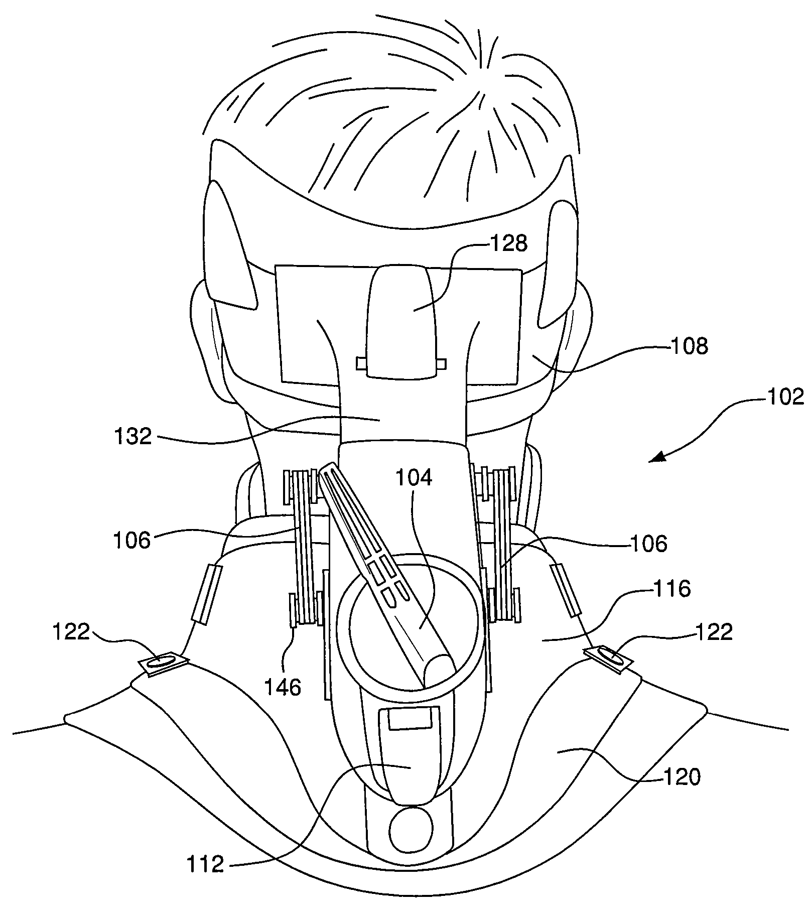
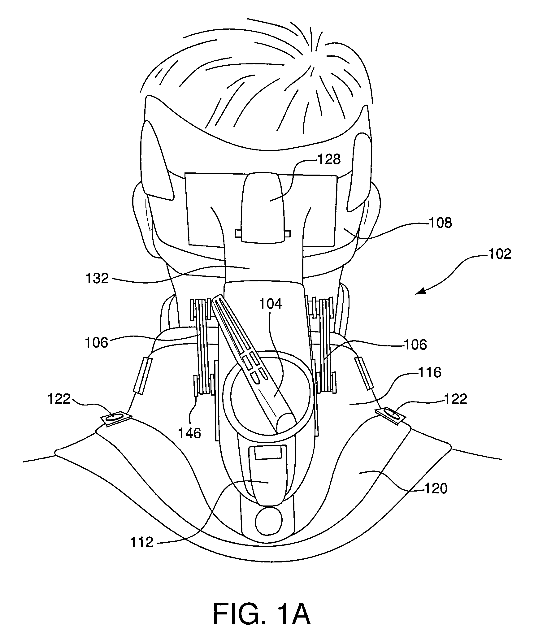
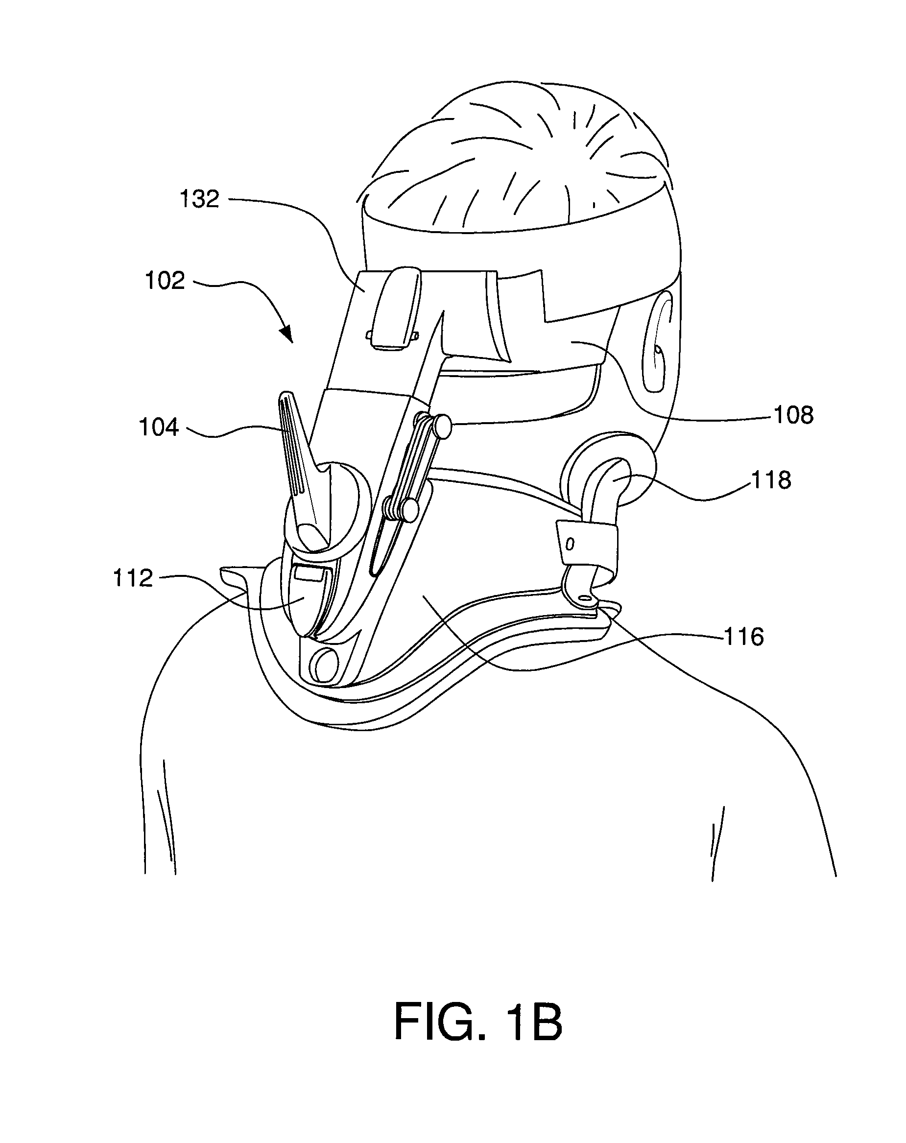
The invention is a traction device that can be used with a cervical collar that has a front counterforce. It can also be integrated into the collar. The collar has a dynamic or fixed support for the wearer's chin to keep the head and spine in alignment during traction. The traction device includes a traction box that is attached to the collar and an occipital support. Different types of collars can be used with the traction device, including a collar that is split into a front and back portion. The technical effect of this invention is to provide a more effective and comfortable way to support and align the head and spine during traction.

Problems solved by technology

Such devices lack mobility, are uncomfortable and rely on patient compliance to be effective.
The device is also not practical or suitable for trauma applications.
These devices, such as the Saunders Hometrac™ and the Pronex®, also are not mobile and not suitable for trauma purposes.
Therefore, patient compliance can be poor.
Prior art mechanisms also do not adequately address the angle at which the head is positioned during traction.
Use of wedges requires patients to be stationary and provides only a limited selection of angles.

Method used


Image

  • Traction collar and method of use
  • Traction collar and method of use
  • Traction collar and method of use

Examples


Embodiment Construction

[0017]Embodiments of the invention include a neck brace for providing intermittent, self-contained traction to the cervical spine for the treatment of chronic neck pain, cervical spine or other medical symptoms or injuries. The device can be manufactured in a light-weight design that is particularly suitable for longitudinal traction for short-term maintenance of cervical reduction following traumatic injury or surgery. Advantageously, this dynamic traction device does not require the patient to be lying down or stationary. The traction device can easily be placed on a patient and adjusted to the desirable constant force. The amount of tension achievable may also be greater than conventional devices. The device grabs onto a patient's anatomy underneath the mastoid processes. This allows the traction to take hold so it does not slide up along the patient's head, providing the ability to impose higher weight traction than with conventional devices. Tension bands or other force-deliver...


PUM


Abstract

A traction device having an adjustable tensioning mechanism, the traction device attachable to a head support and a cervical collar. The tensioning mechanism includes a traction base, a slider slidably connected to the traction base and an adjustment mechanism to force the traction base and slider in opposite directions. One of the traction base or slider is at a fixed longitudinal position with respect to the head support and the other of the traction base or slider is at a fixed longitudinal position with respect to the cervical collar.

Description

[0001]This application is based on, and claims priority to, provisional application having Ser. No. 60 / 734,237 having a filing date of Nov. 7, 2005 entitled Traction Collar.FIELD OF THE INVENTION[0002]The invention relates to a neck brace for providing traction to the cervical spine.BACKGROUND OF THE INVENTION[0003]There are a number of known methods and devices to provide traction to the cervical spine. An over-the-door traction system exists wherein a patient dons a device that circles under their chin and attaches the device to an elevated point, such as the top of a door to provide traction. Such devices lack mobility, are uncomfortable and rely on patient compliance to be effective. The device is also not practical or suitable for trauma applications.[0004]Mechanical or pneumatic devices also exist for cervical spine traction. These devices, such as the Saunders Hometrac™ and the Pronex®, also are not mobile and not suitable for trauma purposes. To use a pneumatic device the pa...

Claims


Application Information

Patent Timeline
Patent Type & Authority Patents(United States)
IPC IPC(8): A61F5/00
CPCA61F5/048A61F5/055A61F5/05883A61H1/0296
Inventor PICKERING, WILLTWEARDY, LISA A. G.GORSEN, ROBERT M.BURNS, CLAY A.
Owner OSSUR HF
Learn More