
Safety latch apparatus

a safety latch and apparatus technology, applied in the field of safety latches, can solve the problems of many access limiting devices becoming a hassle for adults to operate, reducing the usefulness of children and pets passing through the door, and reducing the effectiveness of latching functions, so as to achieve the effect of effectively preventing the latching function, easy and quick disengagement, and preventing the effect of latching

Inactive Publication Date: 2008-11-18
LIND ERIC
View PDF21 Cites 18 Cited by
  • Summary
  • Abstract
  • Description
  • Claims
  • Application Information

AI Technical Summary

Benefits of technology

[0009]The safety latch apparatus of this invention has several features, no single one of which is solely responsible for its desirable attributes. Without limiting the scope of this invention as expressed by the claims that follow, its more prominent features will now be discussed briefly. The present invention provides an apparatus for retaining a movable member, such as a door, of an opening in a closed or substantially closed position relative to a fixed position member, such as a frame of an opening. The safety latch comprises a receiving assembly comprising a single receiving element and a mountable base portion. The safety latch further comprises a latching assembly, engageable with said receiving assembly, comprising a biased compliant arm having a catch element coupled at the end thereof for engaging with said receiving element. The biased compliant arm may be curved to predispose the hook element to engage the receiving element when the opening is utilized. The safety latch is overridable from both sides of an opening by deflecting the compliant arm, after which the biased compliant arm will return to its original latchable position. From the interior of an opening, a user may employ an interactive portion of the latching element for deflecting the latching assembly away from the receiving element. From the exterior of an opening, a user may directly push the compliant arm away from the receiving element. Upon sufficient deflection of the compliant arm, a user may then open the door and bypass engagement of the latch. The safety latch may also easily and quickly be temporarily or permanently disengaged by removing the entire latching assembly or removing the latching element. Disengagement of the latch by removal of the latching assembly is enabled by use of the mounting mechanism feature of this invention, or by simply uninstalling the latching assembly. Disengagement of the latch by removal of the latching element may be enabled by a slideable and lockable latching element that may be slid off the compliant arm thereby effectively preventing the latching function. This slideable latching element feature also may allow a user to pre-select the desired distance a movable member will be allowed to open before latch engagement.
[0010]The safety latch apparatus of this invention may comprise the following features: the latch may be predisposed to a latching position and automatically engages when an unauthorized user attempts to open a door; the latch may be overrideable from either side of a door; the latch may be mountable on any door regardless of the shape of the molding surrounding the door, the latch may be biased to automatically return to a latchable position after overridden; the latch may be easy to install and use; the latch may be adjustable to allow a door to open to various pre-determined angular displacements; the latch may be disengageable thus allowing for a door to open and close freely; the latch may comprise a finger protector which prevents fingers from being smashed in a door; and the latch may be installable on either side of a door and at a variety of vertical positions on a door and doorframe

Problems solved by technology

When a partitioned area contains a hazard, danger, or vulnerability, a latch or lock may secure the door against passage by an unauthorized person or animal.
Thus, their effectiveness in preventing children and pets from passing through the door may be limited.
Regrettably, many access limiting devices become a hassle for adults to operate because of the additional access limitations they create for adult users.
When such devices become obstructive to adults, such devices are frequently disengaged or bypassed, thus eliminating their beneficial use.
However, the engaged safety chain on the interior of the door prohibits an adult user of the door from entering from the exterior side.
Many other access limiting devices are only overrideable from one side of the door and equally become a nuisance to an adult user.
This positive interaction requirement may limit protection compared to systems that lock automatically when the door closes.
For example, a child, the infirmed or pet may be put in danger when a parent or guardian simply forgets to latch a door to a foreseeably dangerous area.
Most latches, however, mount to the molding surrounding a door and therefore any force applied to the latch pulls on the nails mounting the molding.
This significantly weakens the strength of the latches.
Many latches, also, simply are not overrideable from both sides of a door, and require time and effort to effectively put them to use.
Similarly, most safety latches do not comprise a biased locking feature that enables automatic locking without user input, while those that do comprise a bias feature suffer from inconsistency in latch engagement.
Almost all latches on the market today lack the ability to mount to doors with various shapes of molding surrounding them.
Lastly, the prior art safety latches lack the ability to grant to a user the power to adjust the latch to allow a door to open only to a desired displacement.
Prior inventions contemplate devices with some of these features, but none disclose a device capable of all of the listed features.

Method used


Image

  • Safety latch apparatus
  • Safety latch apparatus
  • Safety latch apparatus

Examples


Embodiment Construction

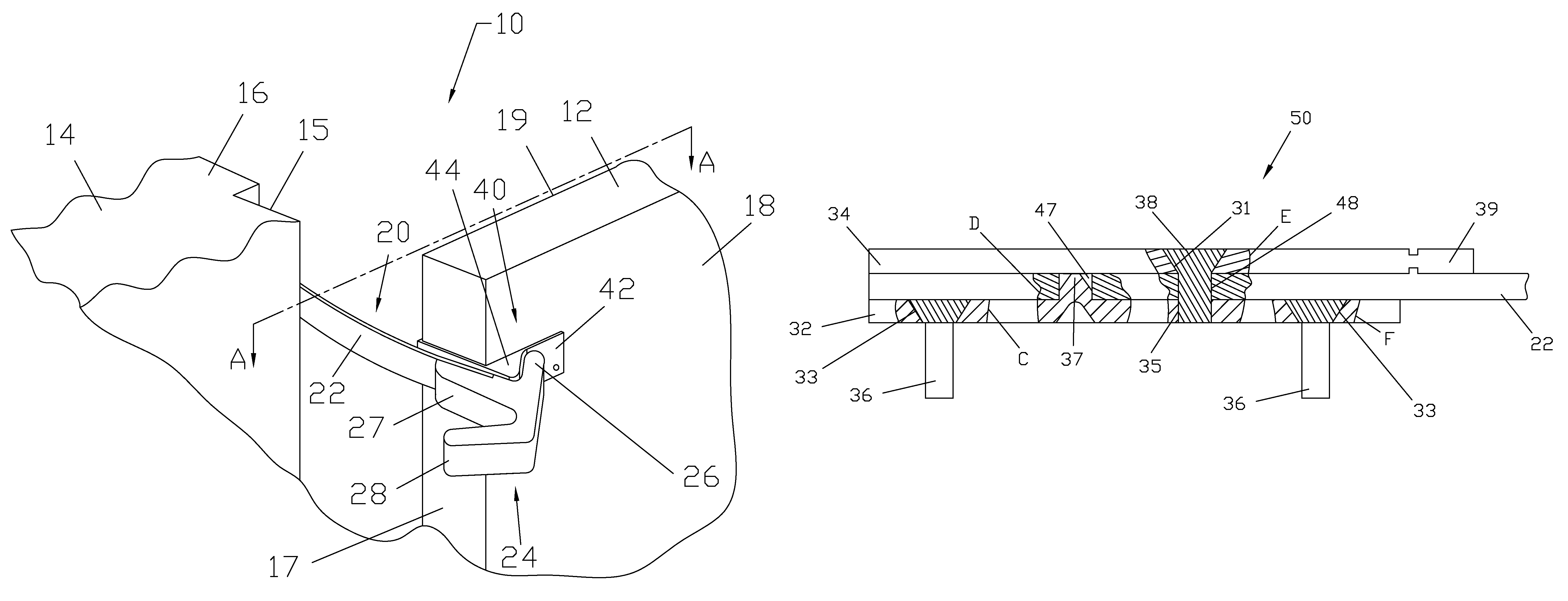
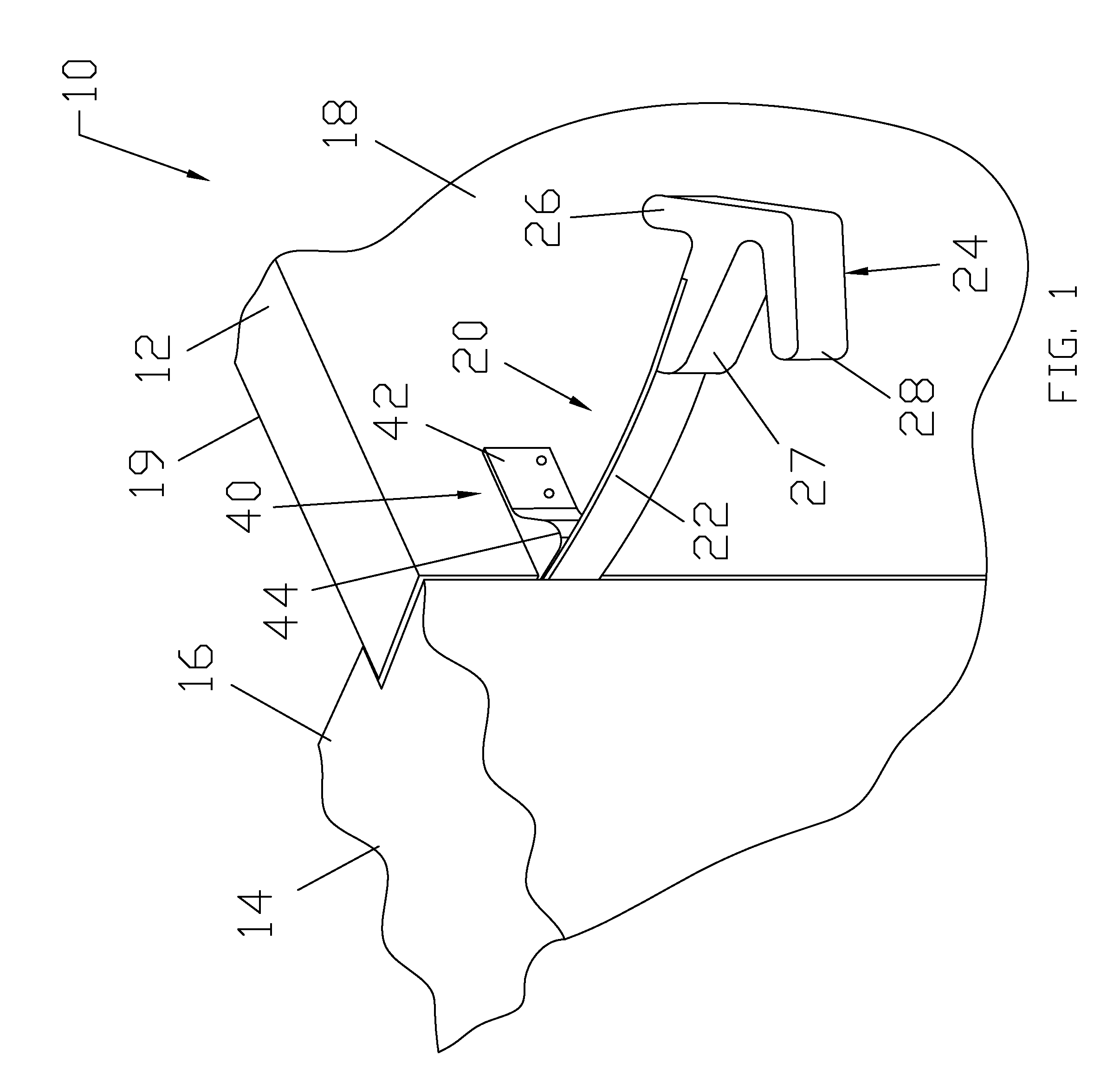
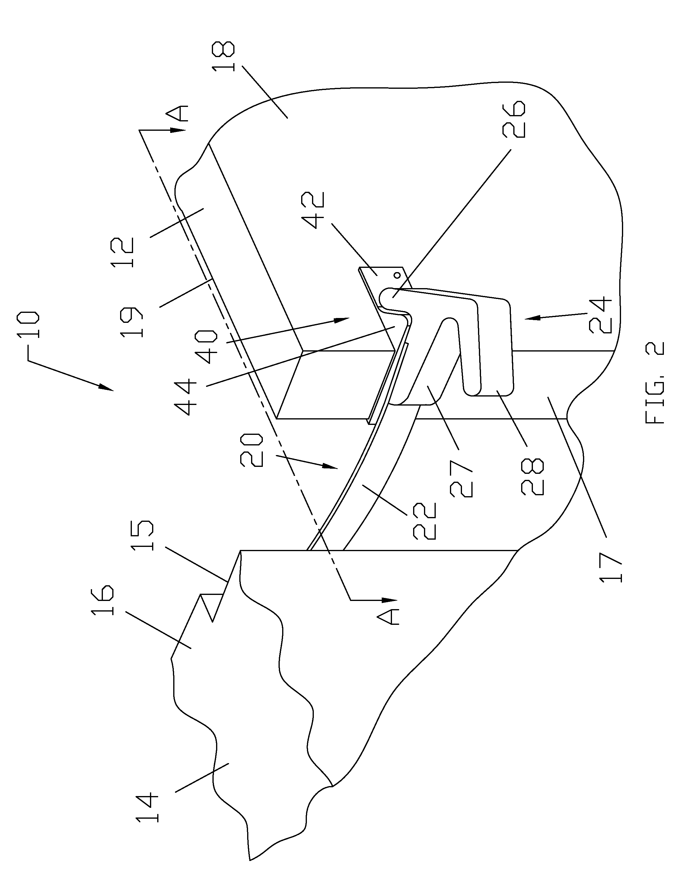
[0033]As discussed above, embodiments of the present invention relate to a safety latch apparatus. Various embodiments of the invention are shown throughout the figures. The figures include common elements in different structural configurations. Common elements are designated with a common base numeral.

[0034]Referring generally to FIGS. 1-5, a safety latch apparatus 10 is depicted for maintaining a swinging door 12 in a substantially closed position relative to a door frame 14, wherein said safety latch apparatus 10 comprises a latching assembly 20 and a receiving assembly 40. Maintaining a swinging door 12 in a substantially closed position may be facilitated by engagement of said latching assembly 20 and said receiving assembly 40. While a swinging door 12 is depicted in the drawings, it is contemplated that the safety latch apparatus 10 may be modified to function on any opening assembly comprising a fixed position member and a movable member. Opening assemblies may include gates...


PUM


Abstract

A safety latch apparatus for retaining a swinging door in a substantially closed position relative to a door frame comprising a receiving assembly having a base portion for mounting to the swinging door or door frame and a single receiving element protruding from said base portion; and a latching assembly engageable with said receiving element and a finger protector. The latching assembly comprising: a biased or curved compliant arm having a hook element coupled at the end, wherein said receiving element engages said hook element at a single point; and a latching assembly mounting mechanism for mounting said complaint arm to said door or door frame such that the receiving assembly and latching assembly are mounted on cooperating doors and door frames. The latching assembly mounting mechanism further comprising an arm retaining plate, and an arm cover plate. The compliant arm also being mountable without a latching assembly mounting mechanism.

Description

BACKGROUND OF THE INVENTION[0001]1. Technical Field[0002]This invention relates to safety latches, and more specifically to biased safety latches that secure a door without positive user engagement.[0003]2. Background Art[0004]A door is generally an opening in a wall (or other partition), often equipped with a hinge and which can be moved to leave the opening accessible, or to close it more or less securely. Hinged doors have typically been the predominant type of door used within homes, businesses, or other structures for egress / regress between various rooms or even the outside of a structure. Doors are used in structures of all kinds, allowing passage between inside and outside, or among internal rooms. The purpose of a door opening is to allow people, animals, and objects to pass, as well as for ventilation. The purpose of door closure is to prevent passage of air, reduce air drafts, create an enclosed space that can be heated or cooled more effectively, privacy and noise reducti...

Claims


Application Information

Patent Timeline
Patent Type & Authority Patents(United States)
IPC IPC(8): E05C19/06
CPCE05C17/36Y10T292/397Y10T292/0902
Inventor LIND, ERIC
Owner LIND ERIC
Learn More