
Flow meter for measuring a flow rate of a flow of a fluid

a flow meter and flow rate technology, applied in the field of flow meters, can solve the problem of difficult mass production of flow meters, and achieve the effect of improving the accuracy of flow meters

Inactive Publication Date: 2008-11-25
OXUS AMERICA
View PDF15 Cites 25 Cited by
  • Summary
  • Abstract
  • Description
  • Claims
  • Application Information

AI Technical Summary

Problems solved by technology

Due to this precision assembly of several parts, mass production of these flow meters is generally very difficult, if available at all.

Method used


Image

  • Flow meter for measuring a flow rate of a flow of a fluid
  • Flow meter for measuring a flow rate of a flow of a fluid

Examples


Embodiment Construction

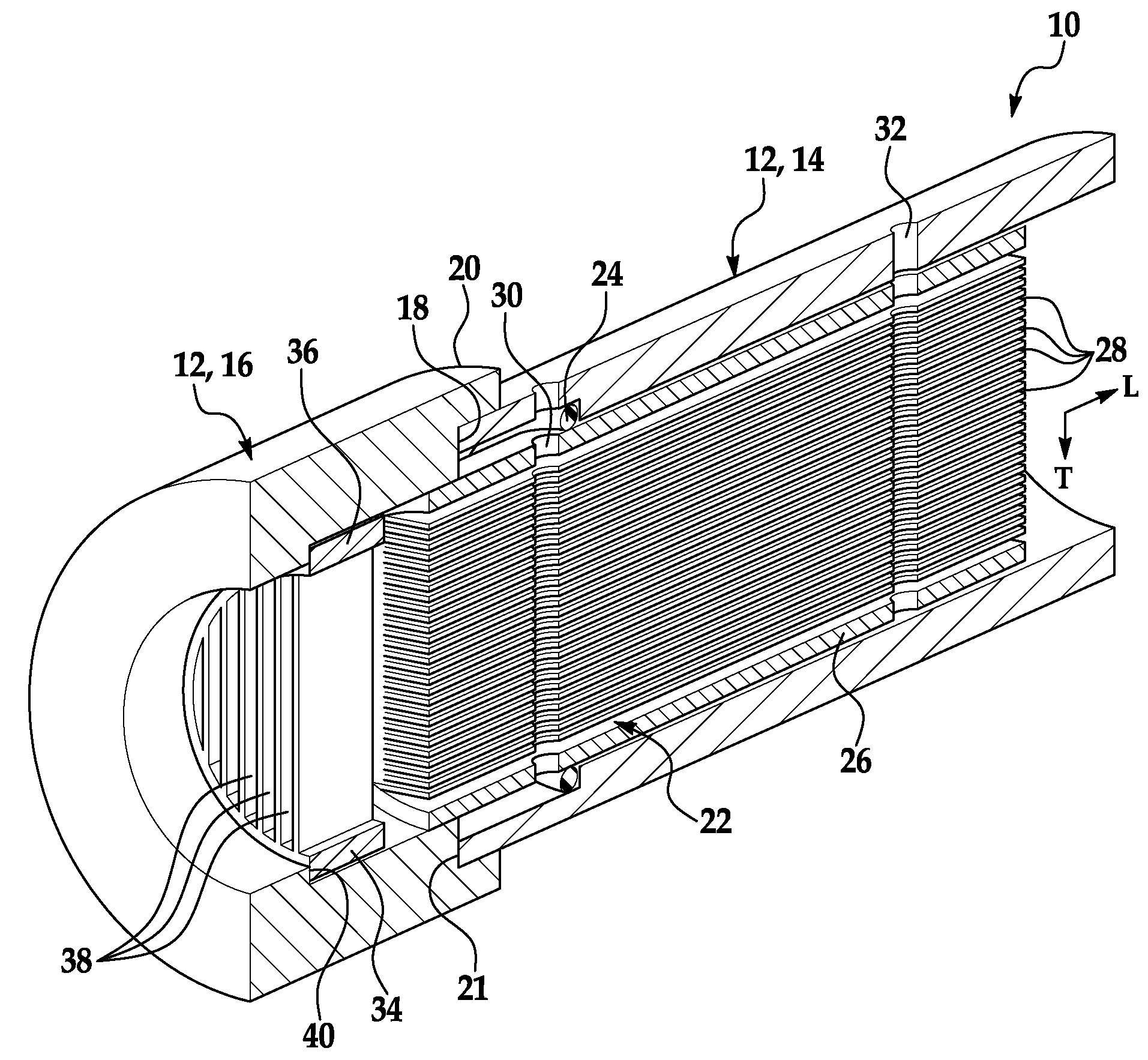
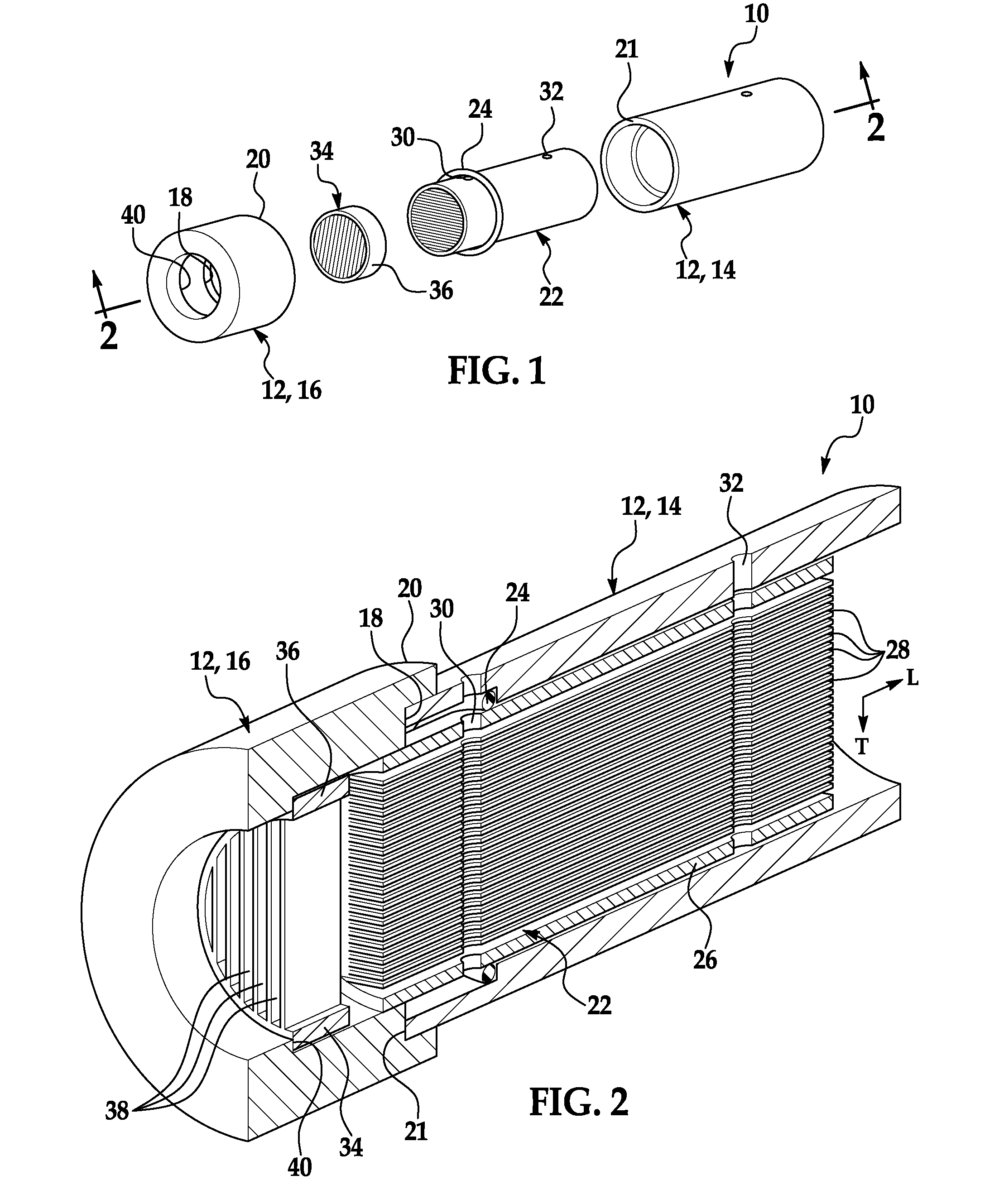
[0009]Embodiment(s) of the flow meter as disclosed herein may be advantageously used to determine the flow rate of a pulsed flow of a fluid substantially instantaneously and with relative certainty. The flow meter is designed to include an integrally formed laminar flow member including a plurality of channels integrally formed therein. The laminar flow member may be easily assembled within a housing member of the flow meter, thereby permitting the flow meter to be produced on a mass production scale. Further, the integrally formed laminar flow member advantageously does not include any intricate and / or delicate parts and, thus, is substantially simple in design and is relatively easy to maintain.

[0010]As defined herein, the term “longitudinal direction” refers to a direction extending lengthwise along the flow meter. Also defined herein, the term “transverse direction” refers to a direction crossing the longitudinal direction.

[0011]The flow meter for measuring a flow rate of a puls...


PUM

PropertyMeasurementUnit
diameteraaaaaaaaaa
response timeaaaaaaaaaa
flow rateaaaaaaaaaa

Abstract

A flow meter for measuring a flow rate of a flow of a fluid includes a housing member including a first section configured to matingly couple with a second section. The flow meter further includes an integrally formed laminar flow member removably held within at least a portion of the first section of the housing member. The laminar flow member includes a body and a plurality of channels integrally formed within the body, wherein each of the plurality of channels is substantially continuous in the longitudinal direction and substantially continuous in the transverse direction.

Description

BACKGROUND[0001]The present disclosure relates generally to flow meters and, more particularly, to a flow meter for measuring a flow rate of a flow of fluid.[0002]Flow meters may be used in, e.g., a pulsed fluid flow system to determine a flow rate of a pulsed flow of fluid traveling through the system. In some instances, the flow meter determines the flow rate of the fluid by measuring a pressure drop across two defined points of a fluid channel formed in the flow meter, and calculating the flow rate based on the pressure drop measurement. Since pulsed flow of a fluid, such as, e.g., oxygen in an oxygen delivery system, includes substantially rapid (e.g., every 100 milliseconds or so) rising and falling flow rates per delivery cycle, the flow rate of the pulsed flow of fluid may be determined by first inducing laminar flow of the fluid through the flow meter. Then the pressure drop of the fluid across the device is measured, and the flow rate is calculated based on a linear relatio...

Claims


Application Information

Patent Timeline
Patent Type & Authority Patents(United States)
IPC IPC(8): G01F1/22
CPCG01F1/48G01F15/00Y10T29/494
Inventor ROSS, DAVID A.THOMPSON, LOREN M.DEDECKER, PAUL G.
Owner OXUS AMERICA
Learn More