Tongue stabilizer for laryngoscope blade

a technology of laryngoscope blade and stabilizer, which is applied in the field of tongue stabilizer for laryngoscope blade, can solve the problems of difficult to quickly provide an appropriate device on the blade to control the tongu

Inactive Publication Date: 2008-12-02
SUN WILLIAM Y
View PDF11 Cites 12 Cited by
  • Summary
  • Abstract
  • Description
  • Claims
  • Application Information

AI Technical Summary

Problems solved by technology

In view of the many different types of blades used, it is difficult to quickly provide an appropriate device on a blade to control the tongue as the intubation process is performed.

Method used


Image

  • Tongue stabilizer for laryngoscope blade
  • Tongue stabilizer for laryngoscope blade

Examples


Embodiment Construction

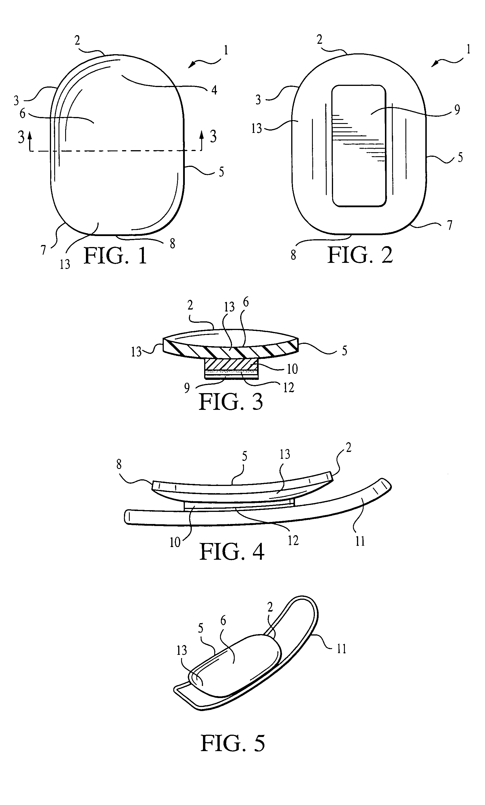
[0014]The tongue stabilizer is shown in FIGS. 1-5. FIG. 1 is a top view of the tongue stabilizer 1 showing a front end 2, front side curve 3, upturned front end 4, side 5, concave central area 6, rear side curve 7 and rear or back end 8 of a tongue-engaging plate 13.

[0015]FIG. 2 is a bottom view of the tongue stabilizer 1 additionally showing the adhesive protective covering or release material 9.

[0016]FIG. 3 is a cross-sectional view taken along the section lines 3-3 of FIG. 1. The adhesive-securing configuration can be seen wherein a foam layer 10 is secured to the tongue stabilizer on one inner surface with an adhesive layer 12 adhered to its second outer surface. To protect the adhesive prior to use, a protective film 9 is held over the adhesive. The upturned front end 2 can be seen as well as the concave or spoon-shape central area 6 with upward extending side edges 5.

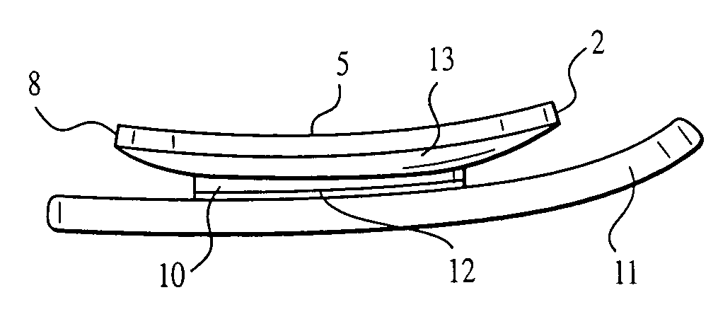
[0017]FIG. 4 is a side view of the tongue stabilizer adhesively secured to a laryngoscope blade 11 showing the ...


PUM


Abstract

A tongue stabilizer includes a tongue-engaging plate that is held on a laryngoscope blade by pressure sensitive adhesive, with a foam strip in-between to compensate for any irregularities between the tongue-engaging plate and the laryngoscope blade. The tongue-engaging plate is cup shape to cradle the tongue to prevent the tongue from interfering with the visibility and process of intubation. A protective strip can be used to cover the adhesive.

Description

BACKGROUND OF THE INVENTION[0001]1. Field of the Invention[0002]A disposable tongue stabilizer is adhesively attached to a laryngoscope blade to position the tongue during intubation.[0003]2. Description of Related Art[0004]In many emergency situations in order to save lives or give anesthetics for surgery in operating rooms, physicians have to use intubation procedures to establish an artificial airway. During these intubation procedures laryngoscopes are used by physicians as an instrument to keep the tongue out of the way in order to visualize the epiglottis so that an endotracheal tube can be inserted into the trachea.[0005]The problem is that all the laryngoscope blades on the market now are narrow and can hold only approximately half of the tongue, so that it is very hard to make the tongue stay on the laryngoscope blade with any degree of stability. The epiglottis is very difficult to visualize and the endotracheal tube is very hard to insert into the trachea as the tongue ge...

Claims


Application Information

Patent Timeline
Patent Type & Authority Patents(United States)
IPC IPC(8): A61B1/267A61B13/00
CPCA61B1/0008A61B1/00105A61B1/267A61B13/00
Inventor SUN, WILLIAM Y.
Owner SUN WILLIAM Y
Why Eureka
Try Eureka