Side sill trim part and method of molding same

a technology of side sills and trim parts, which is applied in the direction of roofs, other domestic objects, transportation and packaging, etc., can solve the problems of difficult removal of parts from molds, difficult molding of deep drawn substantially “c” cross sectioned plastic parts,

Inactive Publication Date: 2008-12-16
GREEN TOKAI
View PDF38 Cites 9 Cited by
  • Summary
  • Abstract
  • Description
  • Claims
  • Application Information

AI Technical Summary

Problems solved by technology

Molding of deep drawn substantially “C” cross sectioned plastic parts is difficult.
If the opposing longitudinally disposed edges converge toward each other, it is difficult to remove the part from the mold in the absence of elaborate sliding mechanisms.

Method used


Image

  • Side sill trim part and method of molding same
  • Side sill trim part and method of molding same
  • Side sill trim part and method of molding same

Examples


Embodiment Construction

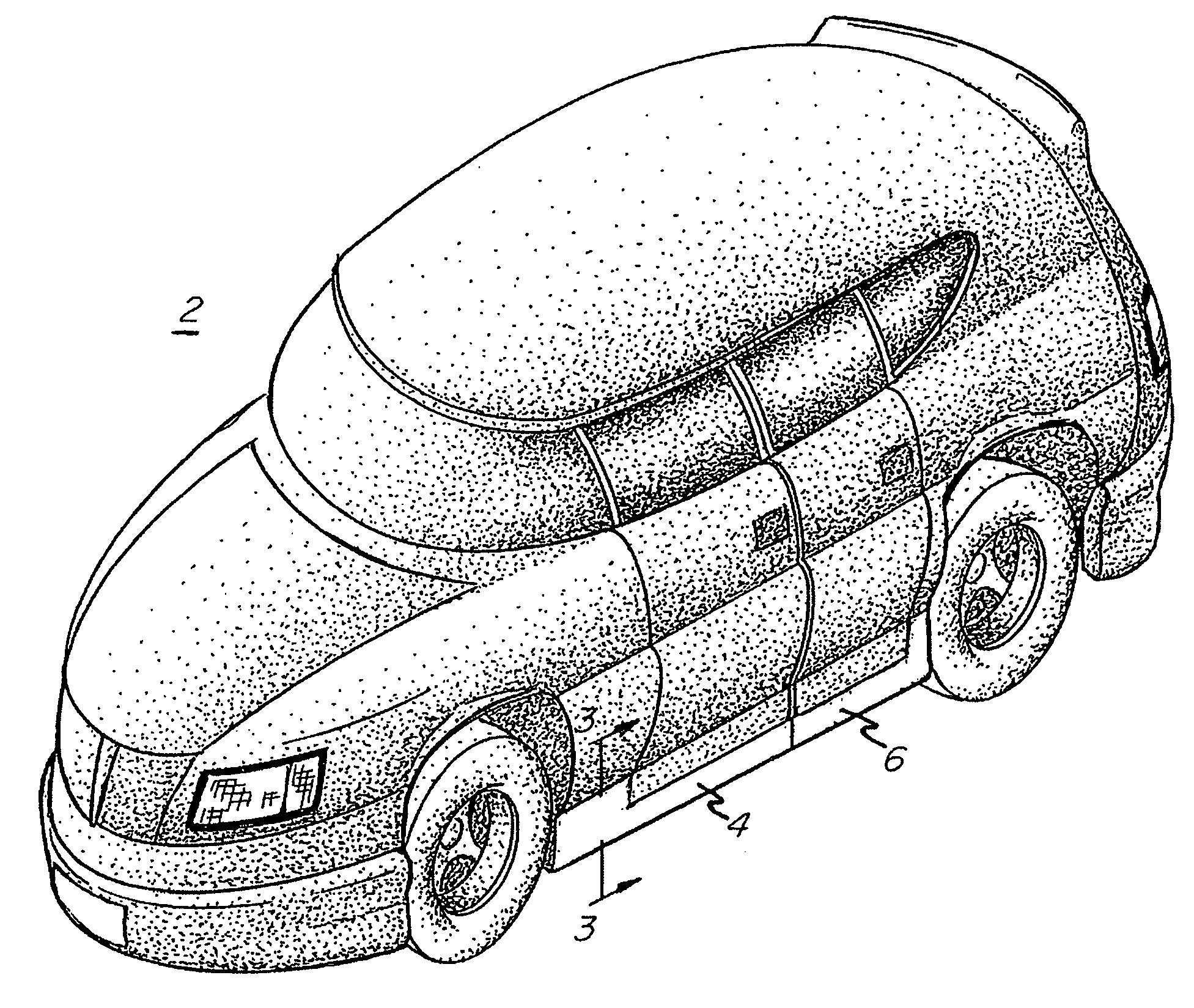
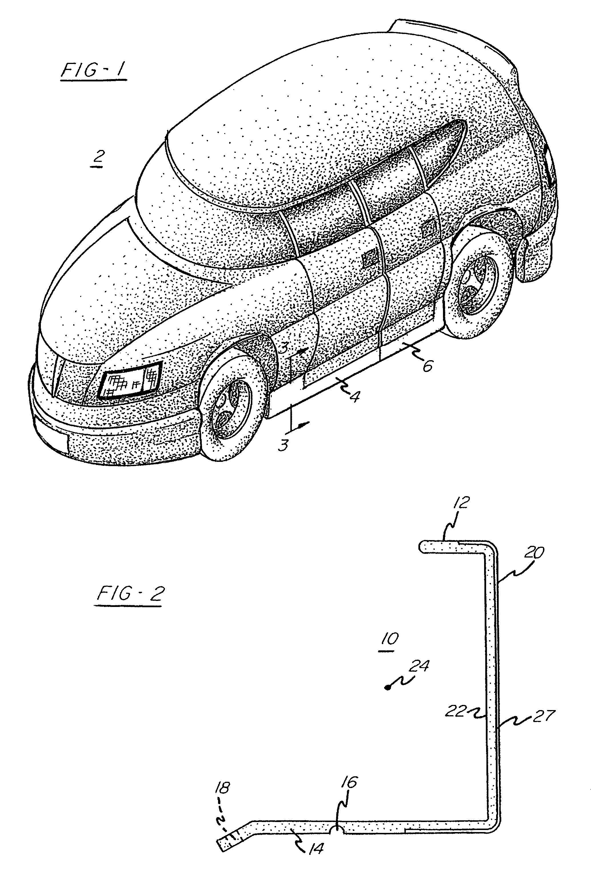
[0015]Turning first to FIG. 1, there is shown an automotive vehicle 2 of the type including a front side sill 4 and rear side sill 6 trim parts. In some instances, these side sill members are referred to as rocker panels. These members are attached below the framing member of the vehicle and help to create an aerodynamic air damming effect as noted above.

[0016]Referring now to FIG. 5, there is shown the inside portion of a finished side sill 500. The inside surface 526 is provided with anchoring means such as cliphouse 504 and associated mounting studs 516 which together with hinged legs 522 serve to mount the side sill member beneath and adjacent the desired frame member. As shown, the side sill member comprises a longitudinal axis 524 extending therealong, and as is common in the art for molding these products, a gas assist channel 502 can be provided in the part. The show surface (not shown in this drawing) may be provided with a paint film or the like to provide a pleasing aesth...


PUM

PropertyMeasurementUnit
angleaaaaaaaaaa
angleaaaaaaaaaa
angleaaaaaaaaaa

Abstract

Improved side sill or rocker panel trim part and methods of molding same are provided. In the methods, a substantially “C” like cross-sectional shaped mold cavity is provided having a pair of terminal cavity portions therein. A living hinge-forming cavity space is provided between a midpoint of the cavity and one of the terminal end portions. The part comprises a longitudinal axis extending therealong and a pair of leg portions and an intermediate section interconnecting the leg portions. The part includes a substantially “C” shaped cross-section transverse to the longitudinal axis with the intermediate section including a show surface side with the legs extending away from the show surface side. A hinge joint is provided adjacent one of the legs so that the part is bendable at the hinge to form a substantially closed “C” position.

Description

CROSS-REFERENCE TO RELATED APPLICATION[0001]This application claims the benefit of U.S. Provisional Patent Application Ser. No. 60 / 401,873 filed Aug. 8, 2002 and is a continuation of U.S. patent application Ser. No. 10 / 524,167 filed Sep. 14, 2005 now abandoned as a U.S. national phase filing under 35 USC §371(c) of International PCT Application No. PCT / US2003 / 024157 filed Aug. 1, 2003. The entire disclosure of the aforementioned U.S. national phase filing is incorporated by reference herein.BACKGROUND OF THE INVENTION[0002]Automotive trim parts and protective molding are often prepared via injection molding techniques with the manufacture of elongated moldings being greatly aided by gas assisted injection molding techniques. For some applications, it is desirable to form deep drawn molded parts wherein the transverse cross section of the elongated part approximates the letter “C”.[0003]For example, it is desirable to provide deep drawn side sill and rocker panel moldings wherein the...

Claims


Application Information

Patent Timeline
Patent Type & Authority Patents(United States)
IPC IPC(8): B60K7/00B29C45/14B29C45/37B29L9/00B29L31/30
CPCB29C45/0055B29C45/0081B29C45/14688B60R13/04B29C45/14778B29C2045/0093B29C2045/14901Y10T428/24479B29L2031/22B29L2031/3005B60R2013/046Y10T428/24198B29L2009/006
Inventor MAKI, RENJI
Owner GREEN TOKAI
Why Eureka
Try Eureka