Imaging lens and imaging apparatus

a technology of imaging lens and imaging apparatus, which is applied in the field of imaging lens, can solve the problems of reducing the degree of design freedom, the imaging lens described in the patent document is not suitable for the image pickup device which requires a high resolving power, and the chromatic aberration and curvature of the image can be corrected

Active Publication Date: 2009-01-20
JIANGXI OFILM OPTICAL CO LTD
View PDF11 Cites 169 Cited by
  • Summary
  • Abstract
  • Description
  • Claims
  • Application Information

AI Technical Summary

Benefits of technology

[0009]With the imaging lens according to the invention, as a whole, the five-lens configuration is adopted which is made up of the first to fifth lenses, so that the number of lenses is increased compared to the conventional imaging lenses which are made up of four lenses and the optimum configuration is realized for each of the constituent lens elements, whereby the resulting imaging lens becomes advantageous in correction of the several aberrations and can deal with the trend of larger image pickup devices and highly fined pixels. By adopting this configuration, a high-performance lens system can be obtained. In particular, an achromatism effect can be obtained by adopting the combination of the positive lens and the negative lens for the first lens and the second lens. On the other hand, in the third lens to the fifth lens, light rays are divided based on image heights, so that correction is implemented for each image height, whereby in the third lens to the fifth lens, correction of curvature of image and distortion is implemented properly while correcting a large negative spherical aberration which has occurred in the first lens and the second lens. A more effective aberration correction becomes possible by using aspherical surfaces for the third lens to the fifth lens. In particular, since the fifth lens is curved to be concave towards the image side in the vicinity of the optical axis while being curved to convex towards the image side along the circumferential edge portion on the image side surface thereof, the aberration correction for each image height is implemented properly, and incident angles of light rays incident on the image pickup device are controlled to be less than or equal to a certain determined angle, whereby irregularity in quantity of light over the whole area of an image forming plane is reduced.
[0011]Furthermore, with the imaging lens according to the invention, by properly adopting the following preferred conditions according to required specifications or the like, a more improved optical performance can be provided.
[0017]In addition, in the imaging lens according to the invention, the first lens and the second lens may be are glass lenses. By forming the first lens and the second lens into the glass lenses, a highly refractive material can be used, and since there is provided a degree of freedom in selecting Abbe numbers, in particular, correction of chromatic aberration and curvature of image can be implemented properly.

Problems solved by technology

In addition, the same issues are occurring with imaging lenses for digital still cameras and reading lenses for film scanners.
While image pickup devices are enlarged in size as the resolving power or number of pixels is increased, with any of the imaging lenses described in the aforesaid patent documents which are made up of four lens elements, correction of curvature of image and chromatic difference of magnification is insufficient for installation in an image pickup device which is ½ inch or larger in size, and hence, the imaging lenses described in the patent documents are not suitable for an image pickup device which requires a high resolving power.
With this material used for plastic lenses, since a double refraction is easy to occur at the time of molding, optical path lengths of light rays which pass through a lens made from polycarbonate are desirably made as short as possible, and hence, when a polycarbonate plastic lens is used for a lens which requires a high resolving power, for example, a thickness of the lens at the center thereof needs to be restricted, this decreasing the degree of freedom in design.
Consequently, such poly carbonate plastic lenses are said to be unsuitable for use as a lens requiring a high resolving power.

Method used


Image

  • Imaging lens and imaging apparatus
  • Imaging lens and imaging apparatus
  • Imaging lens and imaging apparatus

Examples


examples

[0072]Next, specific numerical examples of the imaging lens according to the example of the invention will be described. First to seventh numerical examples will be described altogether below.

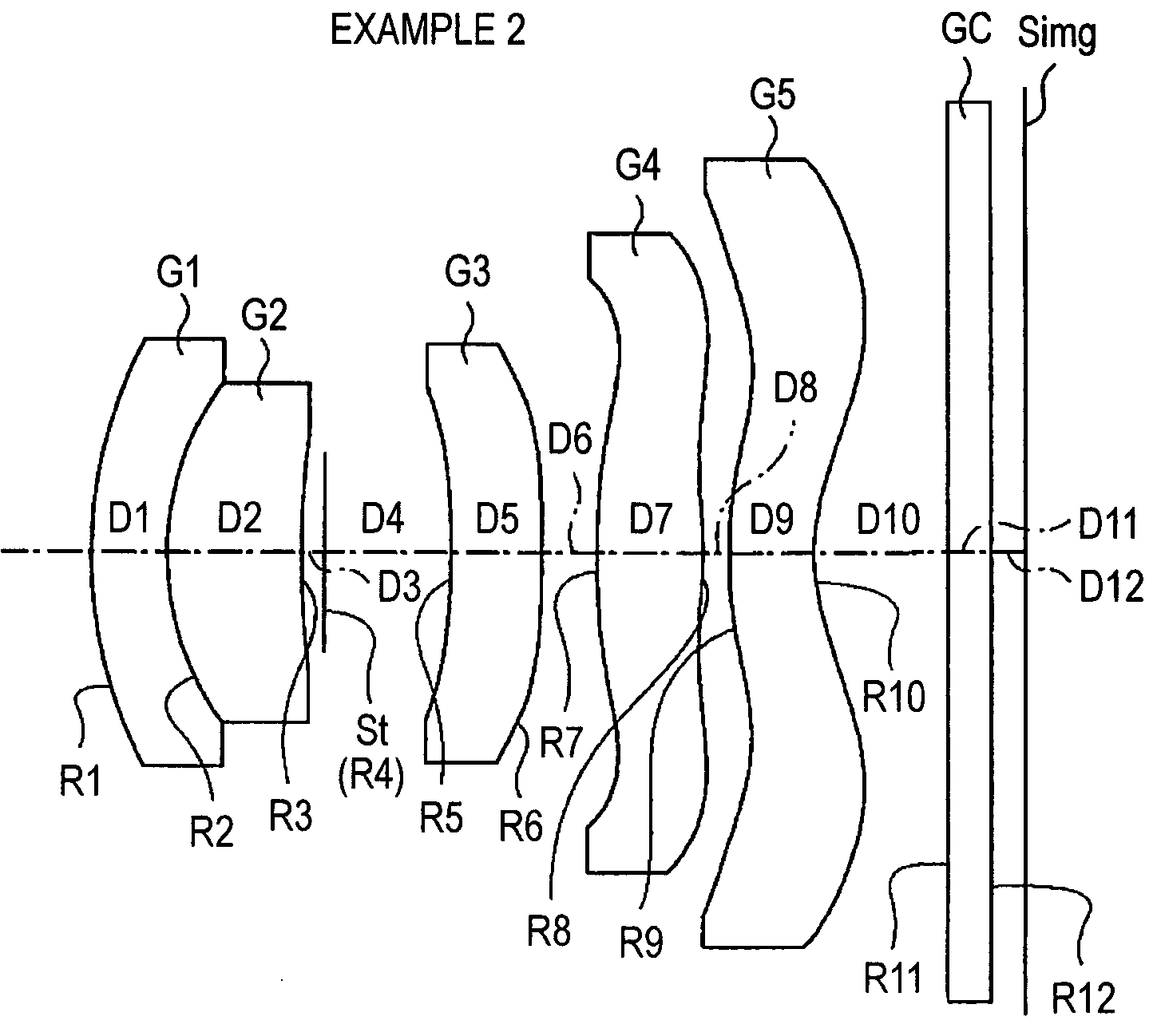
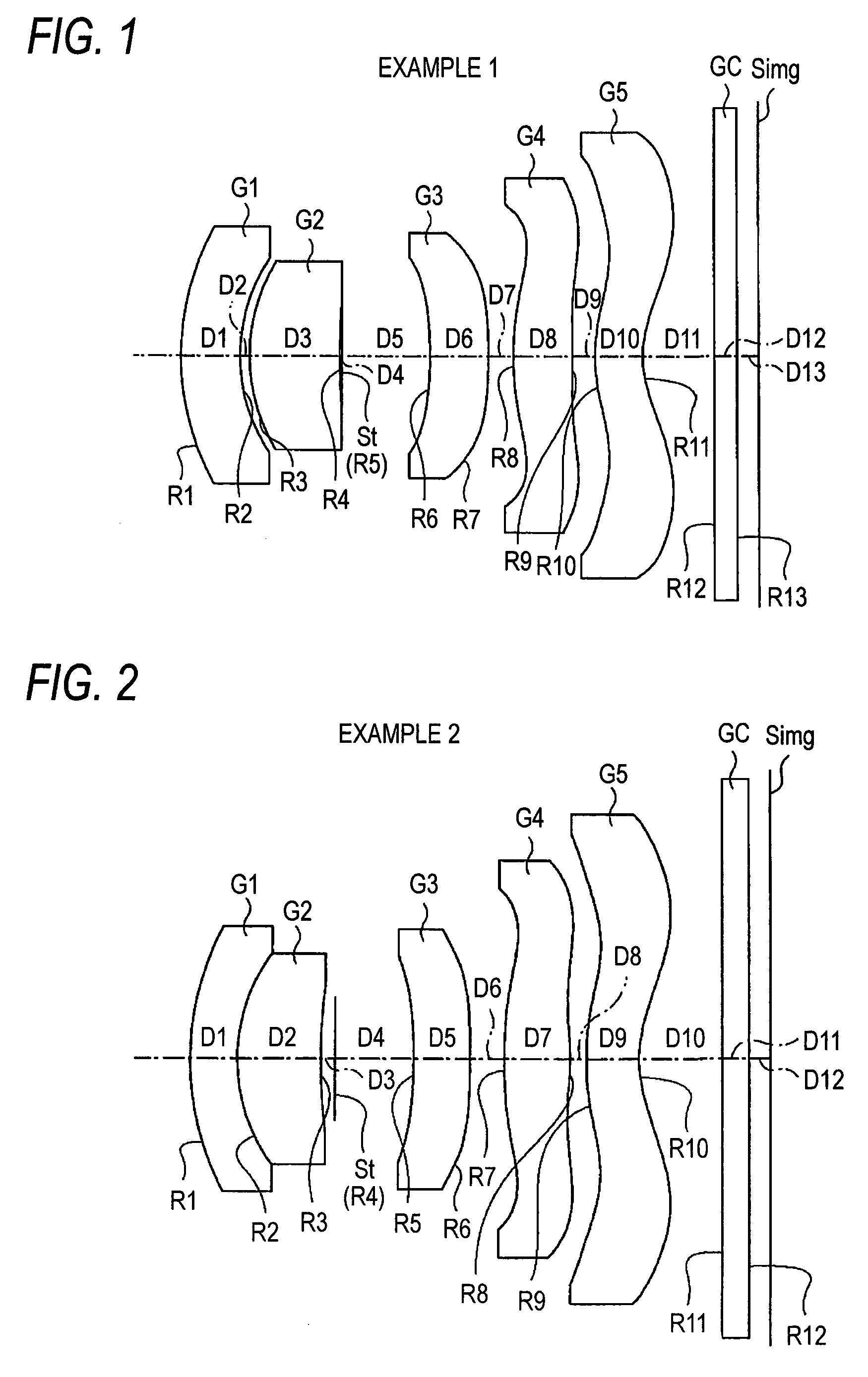
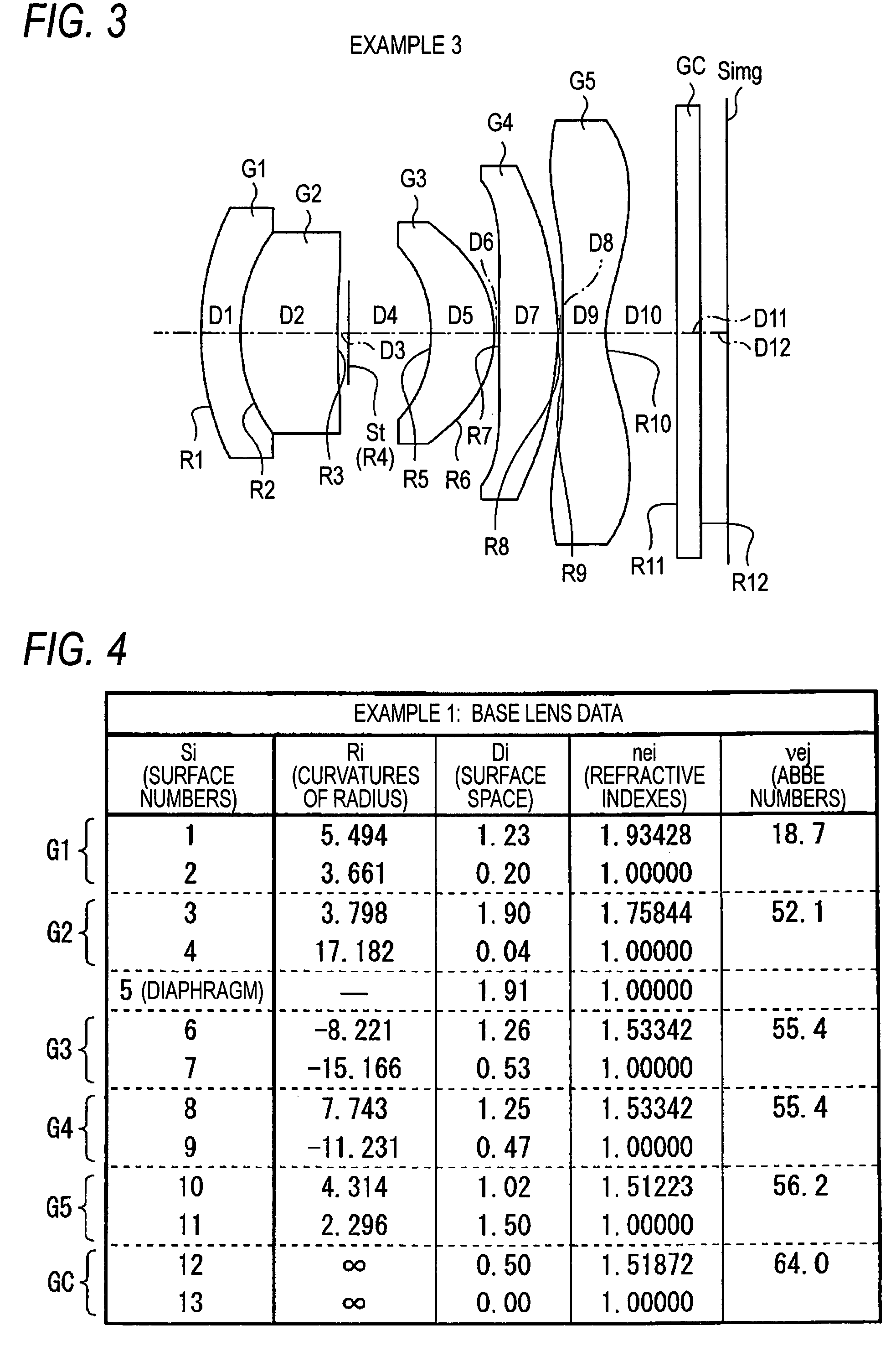
[0073]A specific lens data which corresponds to the configuration of the imaging lens shown in FIG. 1 is shown as Example 1 in FIGS. 4, 5. More particularly, a basic lens data is shown FIG. 4, while a data on the aspherical surfaces is shown in FIG. 5. In a column of surface numbers Si of the lens data shown in FIG. 4, the numbers of ith surfaces (i=1 to 13) are shown to which reference numerals are imparted in an ascending order sequentially-from the object side to the image side of the imaging lens with a numeral 1 imparted to a surface of the constituent lens element which lies in an outermost position on the object side of the imaging lens. In a column of curvatures of radius Ri, the values (mm) of curvatures of radius of the ith surfaces from the object side are shown with reference charac...


PUM


Abstract

An imaging lens comprises, in order arranged from an object side: a first lens of a negative meniscus lens which is curved to be convex towards an object; a second lens of a positive lens which is curbed to be convex on an object side surface thereof; a diaphragm; a third lens which is curved to be convex towards an image; a fourth lens having a positive refractive power in the vicinity of an optical axis; and a fifth lens which is curved to be concave towards the image in the vicinity of the optical axis while being curved to convex towards the image along a circumferential edge portion on an image side surface thereof.

Description

BACKGROUND OF THE INVENTION[0001]1. Field of the Invention[0002]The present invention relates to an imaging lens which forms an image of a subject on an image pickup device such as a CCD (Charge Coupled Device), a CMOS (Complementary Meal Oxide Semiconductor) and the like. The invention also relates to an imaging apparatus for converting an image of a subject which is formed on the image pickup device into an electric signal so as to obtain a digital image of the subject which is used as a mobile phone with a camera, a portable information terminal (PDA: Personal Digital Assistance), a digital still camera, an on-board camera and a monitoring camera, and an image reader for reading an image such as on a film.[0003]2. Description of the Related Art[0004]In recent years, there has been a demand for smaller lenses in the field of camera lenses which are used in mobile phones with a camera, portable information terminals and the like because of smaller installation spaces, and lenses th...

Claims


Application Information

Patent Timeline
Patent Type & Authority Patents(United States)
IPC IPC(8): G02B13/18G02B3/02
CPCG02B9/34G02B9/60G02B13/004G02B13/0045G02B13/006G02B13/22
Inventor MORI, MASAO
Owner JIANGXI OFILM OPTICAL CO LTD
Why Eureka
Try Eureka