Miniature three-piece optical imaging lens with short back focal length

a three-piece, optical imaging technology, applied in the field of optical imaging lenses, can solve the problems of poor effect of spherical ground glass lenses on correction of spherical aberration and astigmatic aberration, and achieve the effect of reducing back focal length and longer focal length

Inactive Publication Date: 2011-09-20
E PIN OPTICAL IND
View PDF20 Cites 1 Cited by
  • Summary
  • Abstract
  • Description
  • Claims
  • Application Information

AI Technical Summary

Benefits of technology

[0007]0.25≤bfTL≤0.4(1)0.001≤Δf≤0.006(2)0.38≤H_Ht≤0.7(3)-0.12≤f1f2≤-0.01(4)0.25≤d3+d5+d7+d9f≤0.5(5)0.7≤f1f≤1.2(6)-0.2≤R21-R22R21+R22≤-0.06(7)wherein f is effective focal length of the optical imaging lens, bf is back focal length, TL is total distance on the optical axis from the object side 11 of the first lens to the image plane, Δ is the absolute value of longitudinal chromatic aberrations at Fraunhofer F curve and C curve wavelengths, H is perpendicular distance from the inflection point on the image side of the third lens to its intersection point of the optical axis, Ht is perpendicular distance from the maximum optical effective point on the image side of the third lens to the optical axis (see FIG. 2), f1 is effective focal length of the first lens, f2 is effective focal length of the second lens, d3 is distance on the optical axis from the image side 12 of the first lens L1 to the object side 21 of the second lens L1, d5 is distance on the optical axis from the image side 22 of the second lens L2 to the object side 31 of the third lens L3, d7 is distance on the optical axis from the image side 32 of the third lens L3 to the object side of the IR cut-off filter 4, d9 is distance on the optical axis from the image side of the IR cut-off filter 4 to the image plane of image sensor 5, R21 is radius of curvature of the object side 21 of the second lens L2 and R22 is radius of curvature of the image side 22 of the second lens L2. Thereby, the imaging lens of the present invention achieves effective aberration correction, high resolution and minimum total length. Therefore, the imaging lens with smaller volume, lower cost has broader applications.

Problems solved by technology

However, the spherical ground glass lenses have poor effect on correction of spherical aberration and astigmatic aberration when being applied under condition of a smaller f number and wide angle of field.

Method used


Image

  • Miniature three-piece optical imaging lens with short back focal length
  • Miniature three-piece optical imaging lens with short back focal length
  • Miniature three-piece optical imaging lens with short back focal length

Examples


first embodiment

The First Embodiment

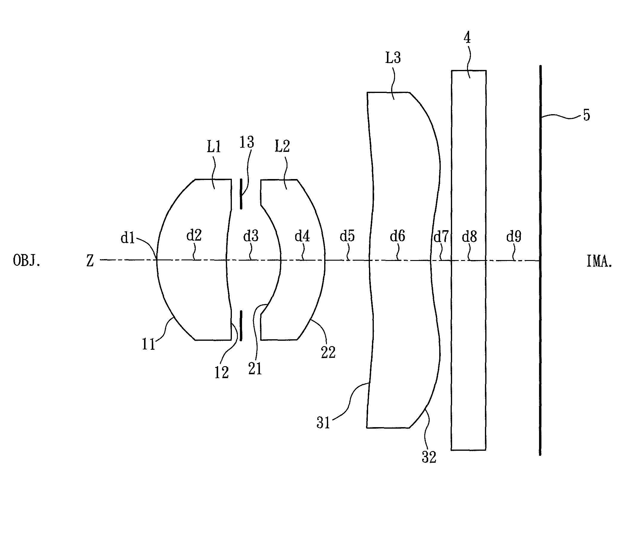
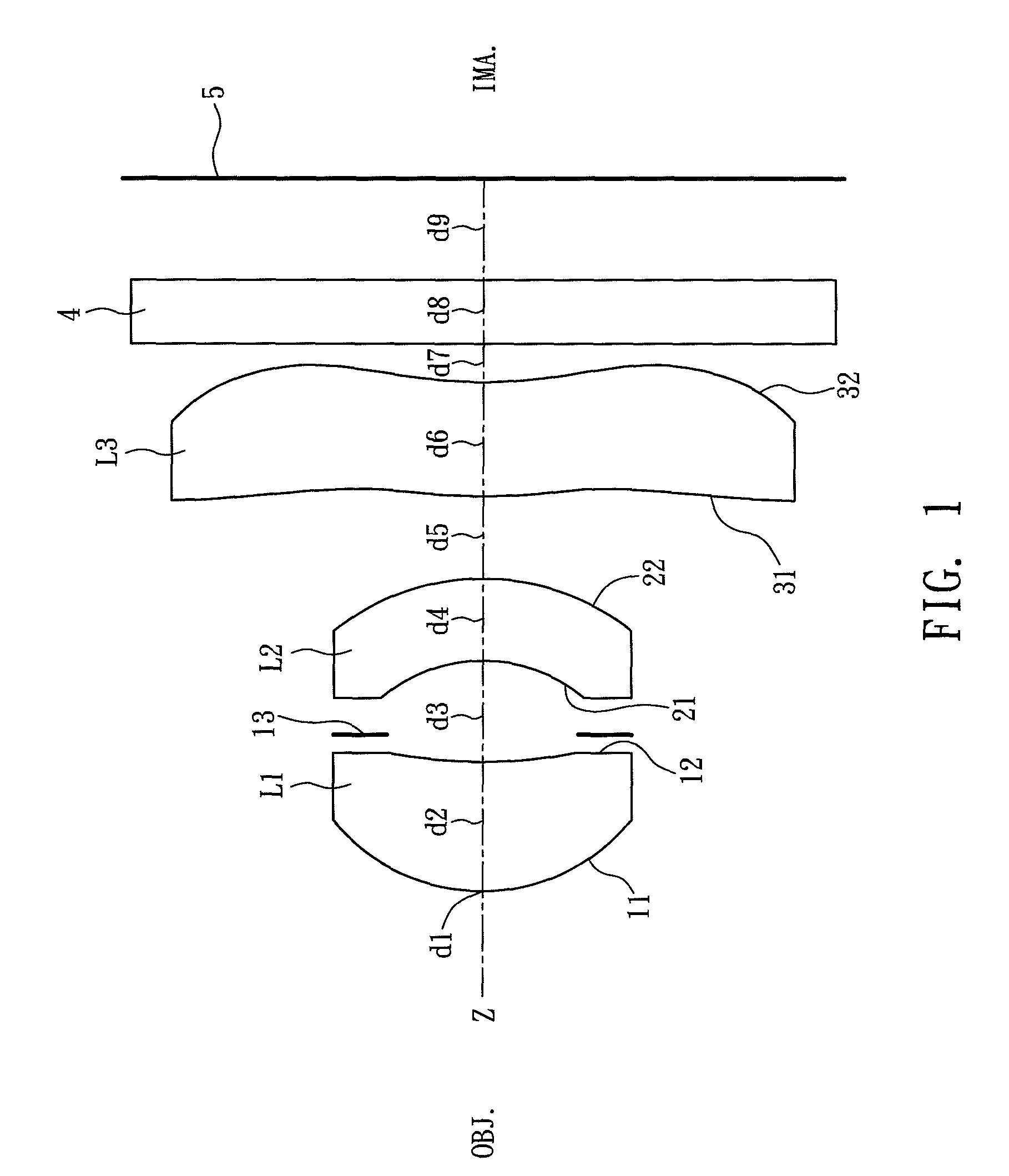
[0036]Refer from FIG. 1 and FIG. 3, 4 showing this embodiment. In order from the object side to the image side, the optical surface numbers, the radius of curvature R (mm) of each optical surface on the optical axis, the on-axis surface spacing d (mm) of each optical surface on the optical axis, the refractive index Nd of each lens, and the Abbe's number vd of each lens is listing in Table 1.

[0037]

TABLE 1Fno = 2.8 f = 2.7468 FOV = 64.0Surface No.Rd (mm)Ndνd1OBJ∞02R1*0.88540.5961.54456.13R2*2.47380.441STOP4R3*−0.75940.3881.585305R4*−0.933170.3246R5*2.74160.541.531567R6*1.75440.1788IR∞0.390.32910IMAGE∞*Aspheric

[0038]The aspheric coefficients of equation (8) of each optical surface are listing in Table 2.

[0039]

TABLE 2KA4A6A8A10A12R1*−1.0201E+001.9252E−012.4606E−01−2.4230E−018.5688E−01−5.1217E−01R2*−5.0000E+016.6491E−01−6.0390E+005.1240E+01−2.3191E+023.9898E+02R3*−6.9428E−01−4.9561E−01−1.7596E+001.5883E+01−6.2732E+015.8837E+01R4*−1.1693E+00−2.9765E−01−4.3670E−023.234...

second embodiment

The Second Embodiment

[0044]Refer FIG. 5-7, Table 4 and Table 5, the symbols thereof are the same as those of the above first embodiment.

[0045]

TABLE 4Fno = 2.8 f = 2.7706 FOV = 63.8Surface No.Rd (mm)Ndνd1OBJ∞02R1*0.89950.5871.54456.13R2*2.49420.449STOP4R3*−0.82240.3711.614265R4*−1.02420.3716R5*1.94390.5061.531567R6*1.36600.1628IR∞0.30090.28410IMAGE∞*Aspheric

[0046]

TABLE 5KA4A6A8A10A12R1*−1.0513E+001.8715E−012.3592E−01−1.8416E−015.4122E−01−1.2992E−01R2*−5.0000E+016.3430E−01−5.6962E+004.9428E+01−2.2786E+023.9898E+02R3*−4.9817E−01−5.1922E−01−8.4273E−018.5060E+00−3.9480E+015.1517E+01R4*−5.2615E−01−3.1071E−012.7776E−011.6700E+00−2.5672E+002.1435E+00R5*−1.0150E+01−5.3093E−016.5799E−01−4.2764E−011.4585E−01−2.0321E+02R6*−1.2160E+01−1.8390E−012.1213E−024.0902E−02−2.9119E−025.4901E−03

[0047]In this embodiment, the first lens L1 is made from plastic that has the refractive index Nd1 of 1.54, and the Abbe's number vd1 of 56.1, the second lens L2 is made from plastic that has the refractive index N...

third embodiment

The Third Embodiment

[0051]Refer to FIG. 8-10, Table 7 and Table 8, the symbols thereof are the same as those of the first embodiment.

[0052]

TABLE 7Fno = 2.8 f = 2.8261 FOV = 61.3Surface No.Rd (mm)Ndνd1OBJ∞02R1*1.08340.6721.54456.13R2*2.73820.545STOP4R3*−1.08100.4271.614265R4*−1.26560.3986R5*1.46470.7071.531567R6*1.19460.2238IR∞0.30090.26910IMAGE∞*Aspheric

[0053]

TABLE 8KA4A6A8A10A12R1*−1.4149E+001.5223E−012.8251E−01−3.6080E−013.5946E−013.4720E−01R2*4.6434E−016.1406E−01−6.9700E+005.6598E+01−1.9326E+022.3541E+02R3*−1.3451E+00−3.4721E−01−8.5815E−029.3063E+00−3.1774E+015.6748E+01R4*−5.4838E−01−2.9738E−011.3360E−011.6725E+00−2.3704E+002.1477E+00R5*−4.9655E+00−5.2364E−016.5918E−01−4.2795E−011.4580E−01−1.9958E−02R6*−8.1455E+00−1.6616E−012.8668E−024.2090E−02−2.9240E−025.3579E−03

[0054]In this embodiment, the first lens L1 is made from plastic that has the refractive index Nd1 of 1.54, and the Abbe's number vd1 of 56.1, the second lens L2 is made from plastic that has the refractive index Nd2 of...


PUM


Abstract

An miniature three-piece optical imaging lens with short back focal length, along an optical axis from the object side to the image side including: a first lens of positive refractive power that is a meniscus aspherical lens having a convex surface on the object side, an aperture stop, a second lens of negative refractive power that is a meniscus aspherical lens having a convex surface on the image side, a third lens of negative refractive power that is an aspherical lens whose center is on the optical axis, while on the lens center the convex surface is on the object side and the concave surface is on the image side. Moreover, from the center of the third lens element toward the edge, the refractive power changes from negative power, through an inflection point, to positive power. Furthermore, the optical imaging lens further satisfies conditions:0.25≤bfTL≤0.4wherein bf is back focal length, TL is total distance on the optical axis from the object side of the first lens to the image plane. Thereby, the imaging lens achieves effective aberration correction, high resolution and minimum total length.

Description

BACKGROUND OF THE INVENTION[0001]The present invention relates to an imaging lens, and more particularly to an optical imaging lens for mobile phones or image sensors such as CCD (Charge Coupled Device) or CMOS (Complementary Metal Oxide Semiconductor) formed by three elements of lens with features of short back focal length, short overall (total) length and low cost.[0002]Due to fast development of modern technology, electronics have becoming more compact and multifunctional. A lot of electronics such as digital cameras, PC (personal computer) cameras, network cameras, mobile phones, even personal digital assistants are equipped with image capturing devices. For convenience of easy-carrying and requirement of humanization, the image capturing devices requires good image quality, compact volume and low cost. Especially for applications on mobile phones, the above requirements are getting more important.[0003]Due to many materials available for making the lens and better correcting e...

Claims


Application Information

Patent Timeline
Patent Type & Authority Patents(United States)
IPC IPC(8): G02B13/18G02B3/02G02B9/12
CPCG02B13/16G02B13/18
Inventor SHYU, SAN-WOEISHIH, BO-YUANKUO, MING-CHE
Owner E PIN OPTICAL IND
Why Eureka
Try Eureka