Optical imaging lens

Inactive Publication Date: 2011-04-07
E PIN OPTICAL IND
View PDF5 Cites 1 Cited by
  • Summary
  • Abstract
  • Description
  • Claims
  • Application Information

AI Technical Summary

Benefits of technology

[0006]Thereby, the imaging lens of the present invention achieves effective aberration correction, high resolu

Problems solved by technology

However, the spherical ground glass lenses have poor effect on correction of spherical aberration and

Method used


Image

  • Optical imaging lens
  • Optical imaging lens
  • Optical imaging lens

Examples


first embodiment

The First Embodiment

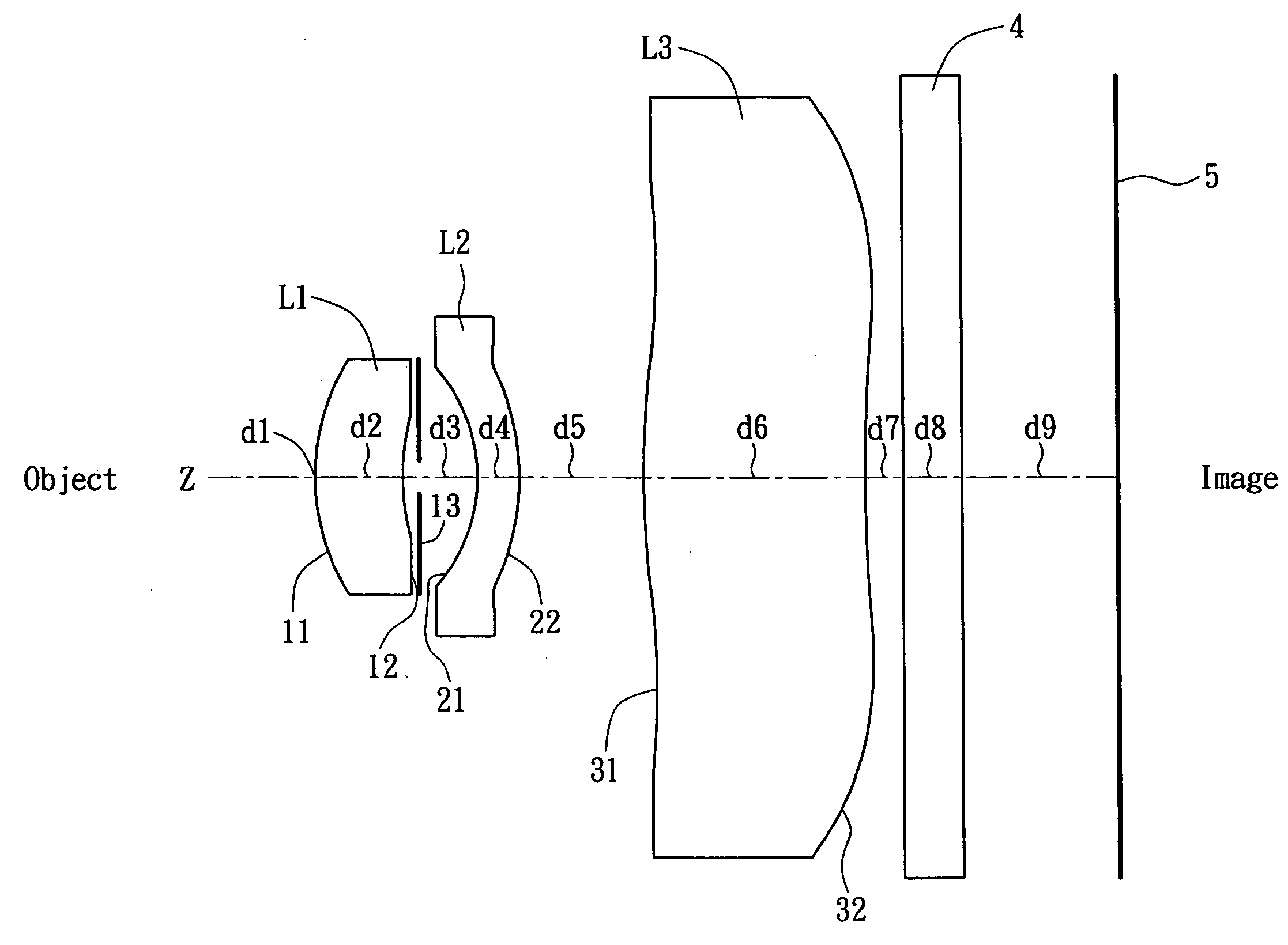
[0025]Refer from FIG. 1 and is showing this embodiment. In order from the object side to the image side, the optical surface numbers, the radius of curvature R (mm) of each optical surface on the optical axis, the on-axis surface spacing d (mm) of each optical surface on the optical axis, the refractive index Nd of each lens, and the Abbe's number vd of each lens is listing in Table 1.

TABLE 1Fno = 2.8 f = 3.3957 FOV = 66.7Surf. No.RdNdνdOBJ∞1 ∞02*1.1382070.47575331.58754662.669992STOP*4.6356630.3332564*−0.65648530.20645991.65061725.9454545*−0.87824810.64434266*4.6330771.0870181.52779143.927137*6.0549670.084958238 ∞0.3BSC73.4702399 ∞0.884900310 ∞IMAGE∞

[0026]In the table 1, the optical surfaces labeled with mark* are aspherical surface. Surf 2, Surf STOP respectively represent the object side 11 and the image side 12 of the first lens element L1, Surf 4, Surf 5 respectively represent the object side 21 and the image side 22 of the second lens element L2, while Surf...

second embodiment

The Second Embodiment

[0030]Refer from FIG. 4 to FIG. 6, Table 3 and Table 4, the symbols thereof are the same as those of the above embodiment.

TABLE 3Fno = 2.8 f = 3.7932 FOV = 61SurfRdNdνdOBJ∞01 1.3822760.5753241.59230457.0077382*6.2887220.4101307STOP*−0.80485380.37524531.69902919.7560574*−1.0733260.55738715*5.6723971.2852071.52204466.9354286*7.0886760.15427077*∞0.3BSC78 ∞1.1319519 ∞010 ∞IMAGE∞

TABLE 4SurfA4A6A8A10A12A1426.13372E−02−1.03515E−013.27534E−01−5.01499E−019.30768E−020STOP−1.71287E−015.88224E−01−3.78531E+009.03207E+00−8.92019E+00042.72501E−011.80280E−021.19260E+00−4.46266E−011.61425E+00−7.79459E+0051.85452E−01−3.40114E−028.01326E−01−9.02915E−013.98681E−0106−6.75944E−03−3.35333E−034.78209E−03−6.28654E−04−5.14523E−06−6.45672E−057−2.32513E−02−3.89653E−032.35579E−03−3.67802E−041.01598E−04−1.74774E−05

[0031]In this embodiment, the first lens element L1 is made from glass that has the refractive index Nd1 of 1.59, and the Abbe's number vd1 of 57.00, the second lens element L2 is ...

third embodiment

The Third Embodiment

[0034]Refer from FIG. 7 to FIG. 9, Table 5 and Table 6, the symbols thereof are the same as those of the first embodiment.

TABLE 5Fno = 2.8 f = 4.3080 FOV = 54.8SurfRdNdνdOBJ∞6001 ∞02*1.3989810.46424611.58633762.338086STOP*5.628090.48349884*−0.80284690.32005231.57393122.7867425*−1.0755381.0383556*6.0741161.0133841.42162979.7929937*6.5917730.11328278 ∞0.3BSC79 ∞1.09891410 ∞IMAGE∞

TABLE 6SurfA4A6A8A10A12A1426.09451E−02−8.73854E−023.70870E−01−4.47208E−015.36996E−020STOP−1.50649E−016.23299E−01−3.72826E+009.11467E+00−8.83643E+00042.73017E−01−1.88753E−021.09131E+00−5.31805E−012.11124E+00−4.82588E+0051.62898E−01−2.57261E−028.51840E−01−8.48133E−011.72359E−0106−2.05279E−02−8.27907E−033.09017E−03−1.52384E−03−4.45357E−04−2.75600E−047−2.58883E−02−3.50832E−032.10350E−03−4.76701E−046.89019E−05−5.20245E−05

[0035]In this embodiment, the first lens element L1 is made from glass that has the refractive index Nd1 of 1.586, and the Abbe's number vd1 of 62.338, the second lens element L...


PUM


Abstract

An optical imaging lens, from object side to image side, includes a positive first lens element that is a meniscus aspherical lens having a convex surface on the object side, an aperture stop, a negative second lens element that is a meniscus aspherical lens having a convex surface on the image side, a positive third lens element that is an aspherical lens while on the lens center, the convex surface is on the object side; and from the center toward the edge, the refractive power changes from positive power, through an inflection point, to negative power. The optical imaging lens satisfies following conditions:
0.5<f1f<1.0;-0.3<f2f<-1.0;0.05<d3f<0.2;R21-R22R21+R22<0.15;
wherein f is effective focal length, f1 and f2 are effective focal length of the first and second lens element respectively, d3 is distance from the image side of the first lens element to the object side of the second lens element, R21 and R22 are radius of curvature of the object side and the image side of the second lens element respectively.

Description

BACKGROUND OF THE INVENTION[0001]The present invention relates to an optical imaging lens, and more particularly to an optical imaging lens for mobile phones or image sensors such as CCD (Charge Coupled Device) or CMOS (Complementary Metal Oxide Semiconductor) formed by three elements of lens with features of high performance, minimized total length and low cost.[0002]Due to fast development of modern technology, electronics have becoming more compact and multifunctional. A lot of electronics such as digital cameras, PC (personal computer) cameras, network cameras, mobile phones, even personal digital assistants are equipped with image capturing devices. For convenience of easy-carrying and requirement of humanization, the image capturing devices requires good image quality, compact volume and low cost. Especially for applications on mobile phones, the above requirements are getting more important.[0003]Due to many materials available for making the lens and better correcting effect...

Claims


Application Information

Patent Timeline
IPC IPC(8): G02B13/18
CPCG02B13/0035
Inventor CHU, CHIA-WEN
Owner E PIN OPTICAL IND
Why Eureka
Try Eureka