In the ear hearing aid utilizing annular acoustic seals

a technology of annular acoustic seals and hearing aids, which is applied in the direction of ear supports, ear moulds/tips acoustic seals, and completely in canal hearing aids. it can solve the problems of unwanted acoustic feedback, custom molded ear worn hearing instruments that have not been fully realized, and achieve the effect of improving the performance and reliability of hard shell acrylic ester copolymer

Inactive Publication Date: 2009-01-20
HEARING SPECIALTIES
View PDF22 Cites 24 Cited by
  • Summary
  • Abstract
  • Description
  • Claims
  • Application Information

AI Technical Summary

Benefits of technology

[0108]“It is an important advantage of the present invention that a hearing aid housing that is matched to a specific auditory canal and that includes various features, e.g. an integrated face plate, a ventilation channel, a tightening protrusion, a battery opening with engaging means, an ear wax guard holder, etc, can be produced automatically with a minimum of manual operations.”
[0109]“Preferably, the shell is produced from a flexible, sweat resistant material. The material should not cause allergic reactions. The shells are preferably polished in a polishing cylinder. The material may be colorless or may be of a color that is close to a desired color. Then, the shell may be colored in a coloring substance of a desired color, e.g. by dipping the shell in the coloring substance.”

Problems solved by technology

Unfortunately, these expectations have not been fully realized.
Historically, custom molded ear worn hearing instruments have been limited to an “acrylic pour” process as the means of construction.
In addition, the pivot action causes displacement of the device resulting in unwanted acoustic feedback.
This problem has caused many shell modifications, thereby compromising the precision approach design process.
Canal motion makes it very difficult to achieve a comfortable, true acoustic seal with hard shell material.
These cavities are transient because they change with jaw motion as a function of time, resulting in impedance changes in the ear canal.
These transients compromise the electroacoustic performance of the hearing aid.
The properties of the hard shells have limitations that require modification to the shell exterior to accommodate anatomical variants and the dynamic nature of the ear canal.
The peripheral acoustic leakage caused by these modifications results in acoustic feedback before sufficient amplification is attained.
The resulting feedback requires electronic modifications to “tweak” the product to a compromised performance.
As a result, the industry still falls well short of audiological optimum.
Unfortunately, soft vinyl materials shrink, discolor, and harden after a relatively short period of wear.
Polyurethane has proven to provide a better acoustic seal than polyvinyl, but has an even shorter wear life.
Silicones have long wear life but are difficult to bond with plastics such as acrylic, a necessary process for the construction of the custom hearing instruments.
The fact remains, that the entire ear is a dynamic acoustic environment and is ill-served by a rigid material.
Unfortunately, fundamental electronic mounting problems result.
The basic issue is the constant flexing of all of the very fine diameter interconnection wires from the micro miniature chip to the receiver, transmitter and face plate.
The potential consequences are wire breakage and micro chip bond failure.
The main cause of this constant flexing is the ear canal's dynamic nature.
The result is a loss of reliability of the complex computer controlled system.
The problem is further complicated by the necessary flexing whenever the instrument is inserted or removed from the patient's ear.
The reliability of the bond between the soft silicone polymer and face plate is also questionable.
The net result is a complex system that solves many of the problems associated with hard shell instruments but suffers from reliable system operation.
In some cases it is not possible to position the hearing aid instrument in the bony portion of the patient's ear canal.

Method used


Image

  • In the ear hearing aid utilizing annular acoustic seals
  • In the ear hearing aid utilizing annular acoustic seals
  • In the ear hearing aid utilizing annular acoustic seals

Examples


Embodiment Construction

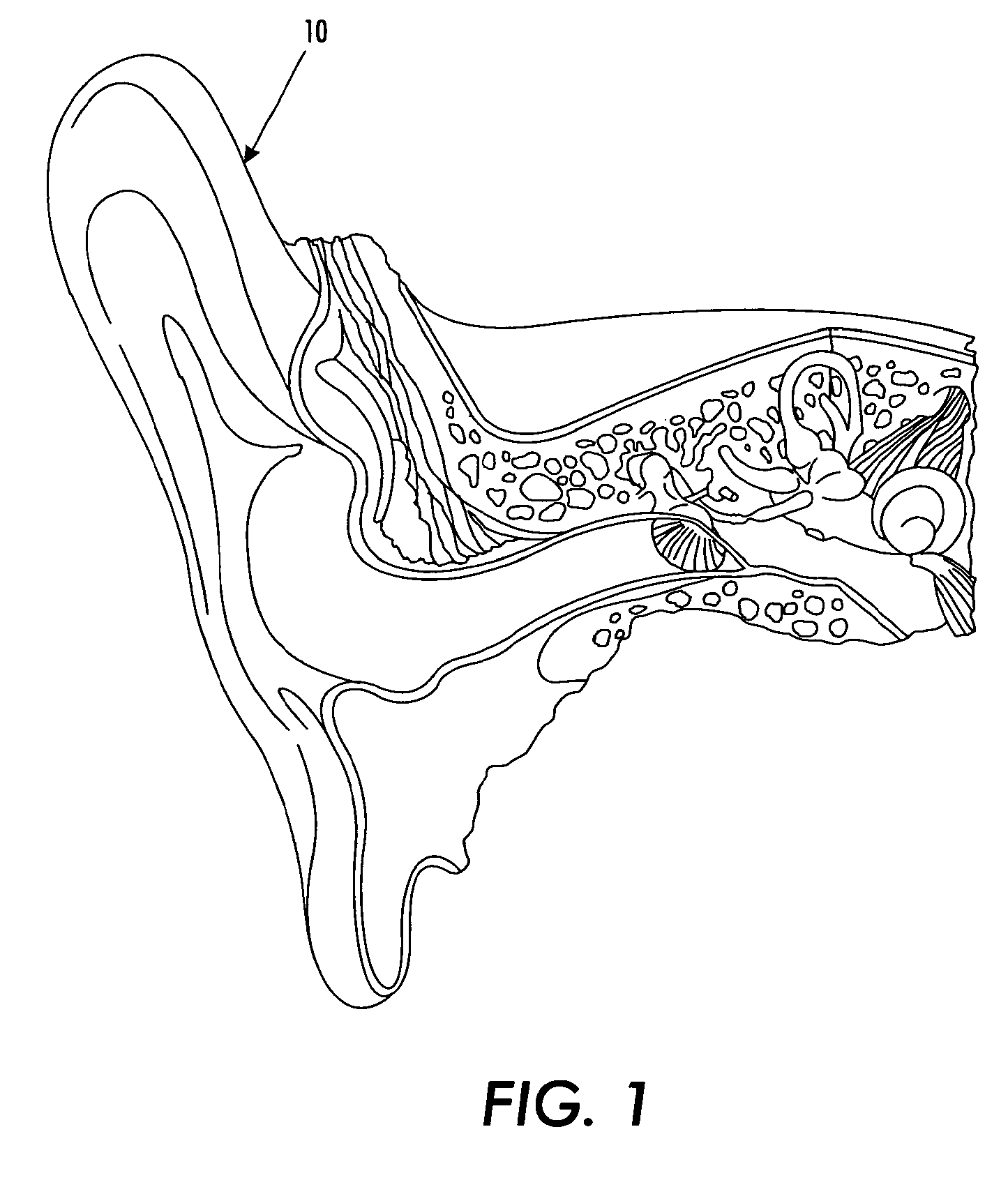
[0051]FIG. 1 is a sectional view of an ear 10 of a human being. This sectional view of the ear 10 is taken from “The Anatomy Chart Series,” Classic Library Edition, ISBN 0-9603730-4-7, Lb. Cat No. 86-071078, Page 21. In the embodiment depicted, the ear 10 is a right ear.

[0052]Reference also may be had, e.g. FIG. 1 of U.S. Pat. No. 6,228,020, which is “. . . a sectional elevational view of a user's hearing area to show the anatomy thereof.” The entire disclosure of such United States patent is hereby incorporated by reference into this specification.

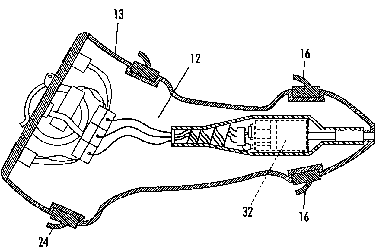
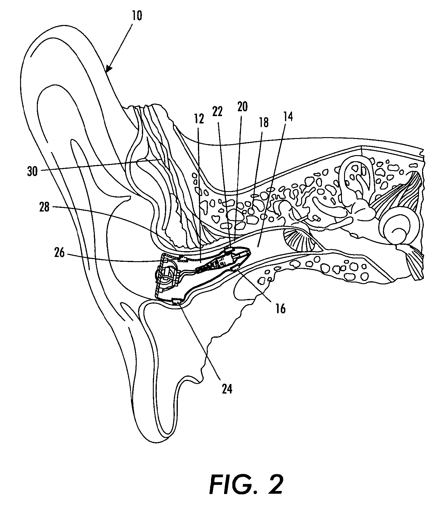
[0053]FIG. 2 is a sectional view of the ear 10 with a hearing aid assembly 12 disposed within the ear canal channel 14. The hearing aid assembly 12 is comprised of a first seal 16 that is disposed just prior to the bony portion 18 of the ear. In the embodiment depicted, the bony portion 18 starts at point 20. The distance between the end 22 of the first seal 16 and the point 20 is preferably no greater than about 2 millimeters and, more p...


PUM


Abstract

Disclosed is a hearing aid assembly wherein the hearing aid is comprised of an acoustic receiver, an acoustic transmitter, and a body, and an annular channel, wherein the acoustic receiver is designed to fit into a external acoustic meatus of an ear, the acoustic transmitter is designed to fit into a inner ear canal, and the generally cylindrical body is disposed between the receiver and the transmitter, the annular channel is disposed on the surface of the body such that it circumscribes the body's circumference. The annular channel is adapted to receive an annular ring which functions as an acoustic seal and which, in one preferred embodiment, has a T-shaped cross-section.

Description

CROSS-REFERENCE TO RELATED PATENT APPLICATIONS[0001]This application is a continuation-in-part of applicants' patent application Ser. No. 10 / 992,040, filed on Nov. 18, 2004 now U.S. Pat. No. 7,164,775, which claims the benefit of U.S. Ser. No. 60 / 525,911, filed on Dec. 1, 2003. The entire content of each of the aforementioned applications is hereby incorporated by reference into this specification.FIELD OF THE INVENTION[0002]A hearing aid assembly with a housing whose outer surface contains one or more annular channels within which are disposed a compliant acoustic material ring seal that preferably has a cross-sectional shape similar to that of T.BACKGROUND OF THE INVENTION[0003]Hearing aid assemblies are well known to those skilled in the art. By way of illustration and not limitation, reference may be had to U.S. Pat. No. 6,228,020 (compliant hearing aid), U.S. Pat. No. 6,438,244 (hearing aid construction with electronic components encapsulated in soft polymeric body), U.S. Pat. ...

Claims


Application Information

Patent Timeline
Patent Type & Authority Patents(United States)
IPC IPC(8): H04R25/02H04R25/00
CPCH04R25/652H04R25/658H04R2225/023H04R2225/77H04R2460/15B33Y80/00
Inventor MEYER, JOHN A.PENMAN, DEAN THOMAS
Owner HEARING SPECIALTIES
Why Eureka
Try Eureka