Method and device for optically examining an object

a technology of optical examination and object, applied in the field of optical examination of objects, can solve the problems of limiting the speed with which individual image stacks can be recorded, high cost of optical components employed in confocal scanning microscopy, and requiring a great deal of adjustment work, so as to improve the computation speed, the sharp image area of each plane can be ascertained more easily, and the effect of increasing the computation speed

Inactive Publication Date: 2009-02-24
LEICA MICROSYSTEMS CMS GMBH
View PDF22 Cites 12 Cited by
  • Summary
  • Abstract
  • Description
  • Claims
  • Application Information

AI Technical Summary

Benefits of technology

[0015]The effect of the deconvolution is that the imaging errors associated with the imaging system employed are removed from each plane image, in other words, the errors can be calculated out. Details on the mathematical deconvolution are likewise known to the skilled person from technical books. Advantageously, every single plane image is deconvoluted even before the start of the computation process that is use to ascertain and separate the sharp image areas. In this manner, each plane clearly acquires greater sharpness and the sharp image areas of each plane can be ascertained more easily. In order to increase the computation speed, it is also possible to only carry out the deconvolution with the multifocus image. However, the result of the deconvolution can be worse than with a deconvolution of all of the individual images, followed

Problems solved by technology

The optical components employed in confocal scanning microscopy, however, are very expensive and, in addition to sophisticated technical knowledge, they also require a great deal of adjustment work.
The high weight of the stage and the resultant inertia of th

Method used


Image

  • Method and device for optically examining an object
  • Method and device for optically examining an object
  • Method and device for optically examining an object

Examples


Embodiment Construction

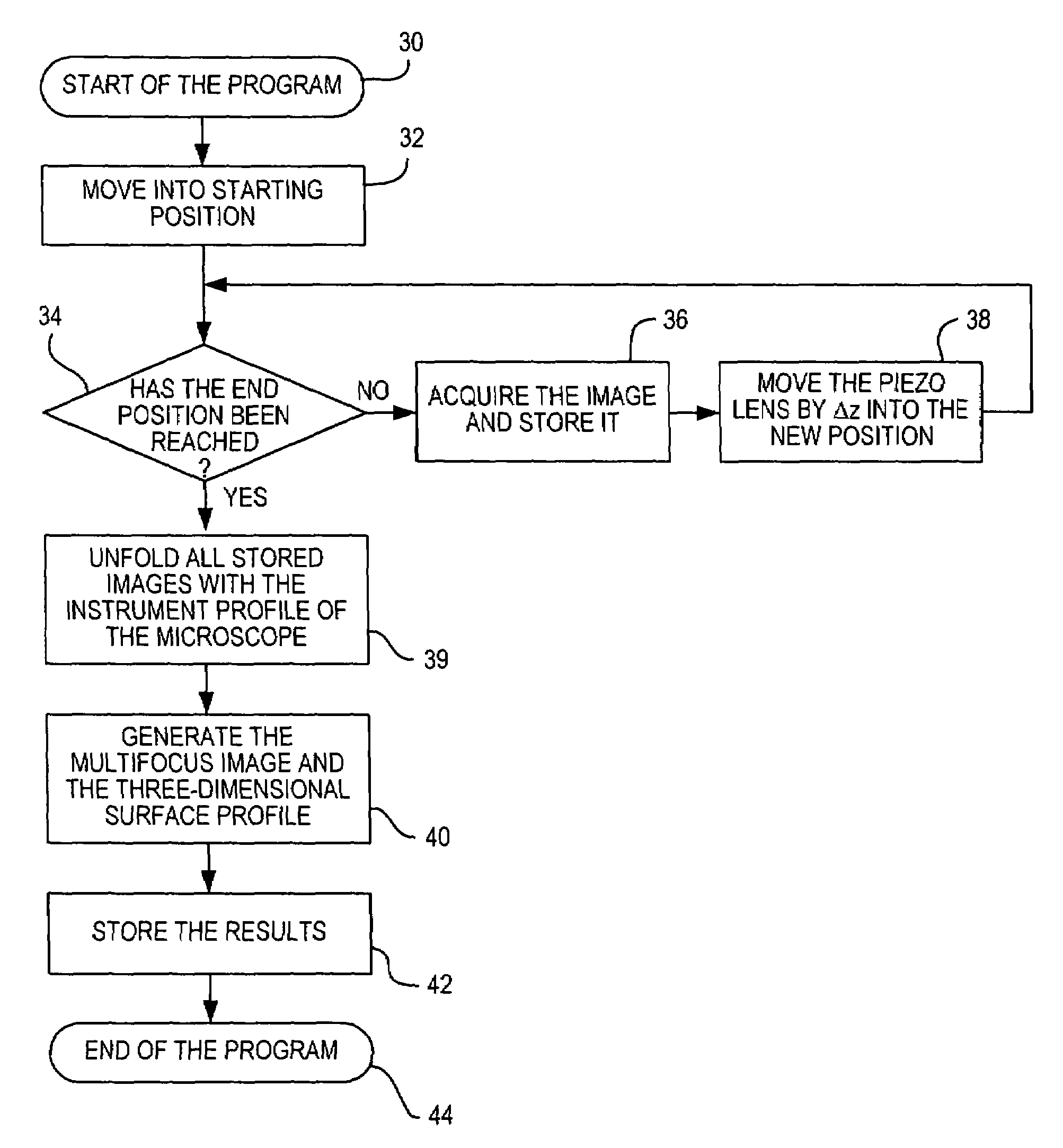
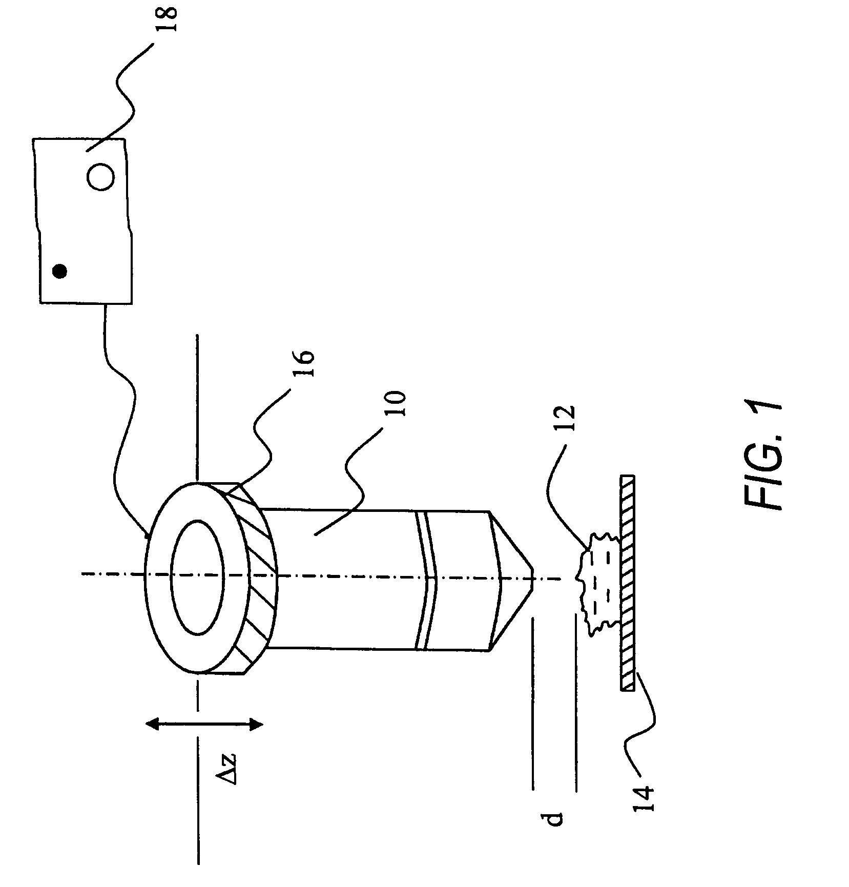
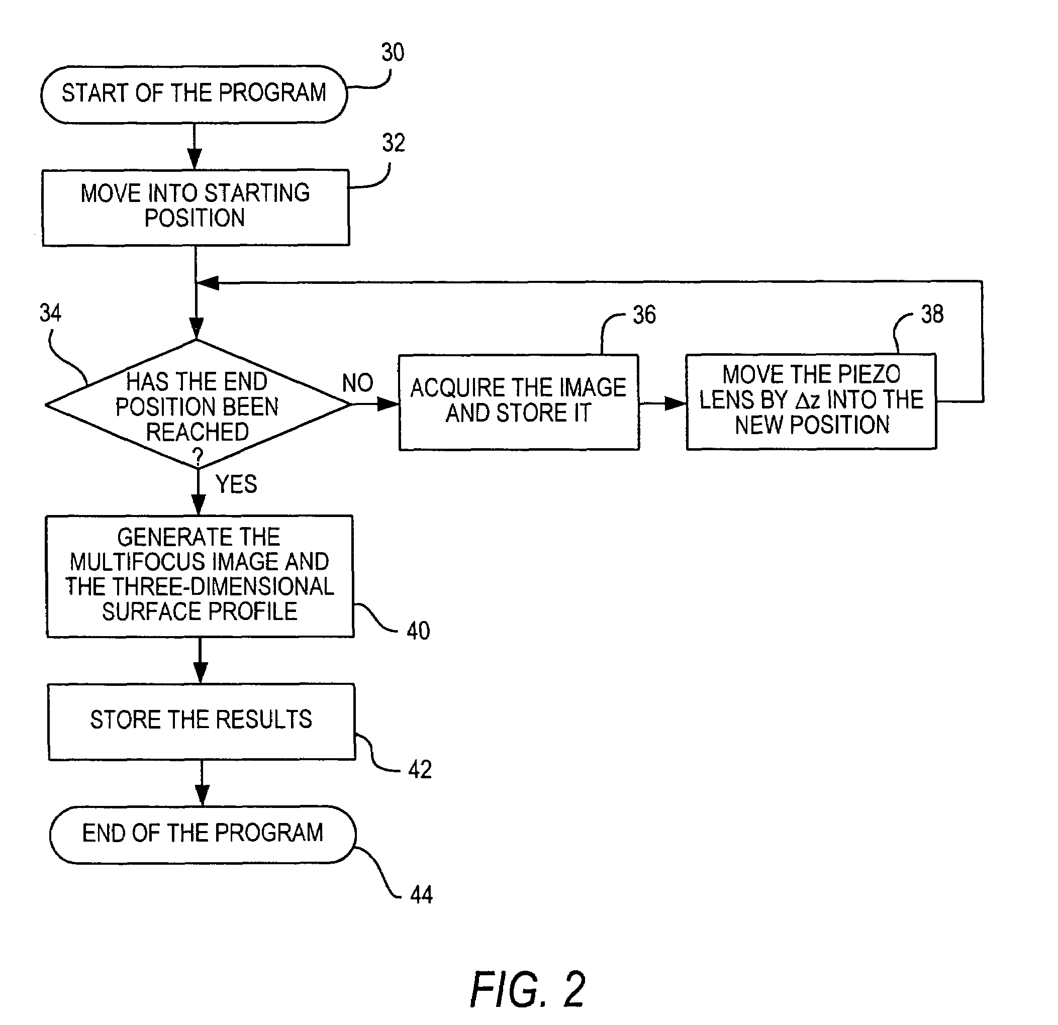
[0042]FIG. 1 schematically shows a section of a device for examining an object with a piezo-controlled lens. A lens 10 serves to examine an object 12 that has been placed onto an object stage 14. In order to generate an image with depth of focus as well as a three-dimensional surface profile of this object, according to the invention, a series of individual images are recorded, whereby each of these individual images lies in different z planes of the specimen. For this purpose, the focus of the lens 10 in the specimen must be positioned in such a way that it lies in the desired plane. That is achieved by adjusting the distance d between the lens and the object. In order to do so, the lens is provided with a piezo actuator 16 that is coupled to a control device 18. The piezo actuator 16 can be actuated with the control device 18 so that the lens 10 is moved, as is indicated by the double arrow. In this manner, the focus inside the object 12 can be adjusted with the piezo-controlled l...


PUM


Abstract

A device for optically examining an object includes a lens, an object stage for receiving the object, and an image-recording apparatus for recording a series of individual images of the object in a number of planes. A piezo-controlled apparatus is provided for adjusting the distance between the lens and the object, and an image-generating apparatus is provided for generating a multifocus image from the series of individual images.

Description

[0001]The invention relates to a device for optically examining an object, having a lens and an object stage for receiving the object and it also relates to a method for optically examining an object.BACKGROUND[0002]When specimens are examined under a microscope, there is often a need to reconstruct the three-dimensional shape of the surface of the object. Confocal scanning microscopy, for example, can be employed for this purpose. In such a case, a specimen is scanned point-by point with the focus of a light beam in a plane, so that an image is obtained in this image plane, although with only a small depth of focus. By recording several different planes and appropriately processing the images, the object can then be imaged three-dimensionally. Such a confocal scanning microscope method is known, for example, from U.S. Pat. No. 6,128,077. The optical components employed in confocal scanning microscopy, however, are very expensive and, in addition to sophisticated technical knowledge...

Claims


Application Information

Patent Timeline
IPC IPC(8): G01B11/24G02B21/00G02B21/26G02B21/36
CPCG02B21/002G02B21/367
Inventor SIECKMANN, FRANK
Owner LEICA MICROSYSTEMS CMS GMBH
Why Eureka
Try Eureka