Sterile transfer battery container

a battery container and sterile technology, applied in the field of surgical powered instruments, can solve the problems of non-sterile battery exposure, failure of sterile transfer system, or other failures

Active Publication Date: 2009-03-10
LINVATEC
View PDF1 Cites 1192 Cited by
  • Summary
  • Abstract
  • Description
  • Claims
  • Application Information

AI Technical Summary

Problems solved by technology

Due to the vibrations associated with the powered surgical instruments, it sometimes occurs that known designs of sterile transfer systems become open (thus exposing the non-sterile battery) or otherwise fail (by, for example, the sterilized container becoming detached from the instrument).

Method used


Image

  • Sterile transfer battery container
  • Sterile transfer battery container
  • Sterile transfer battery container

Examples


Embodiment Construction

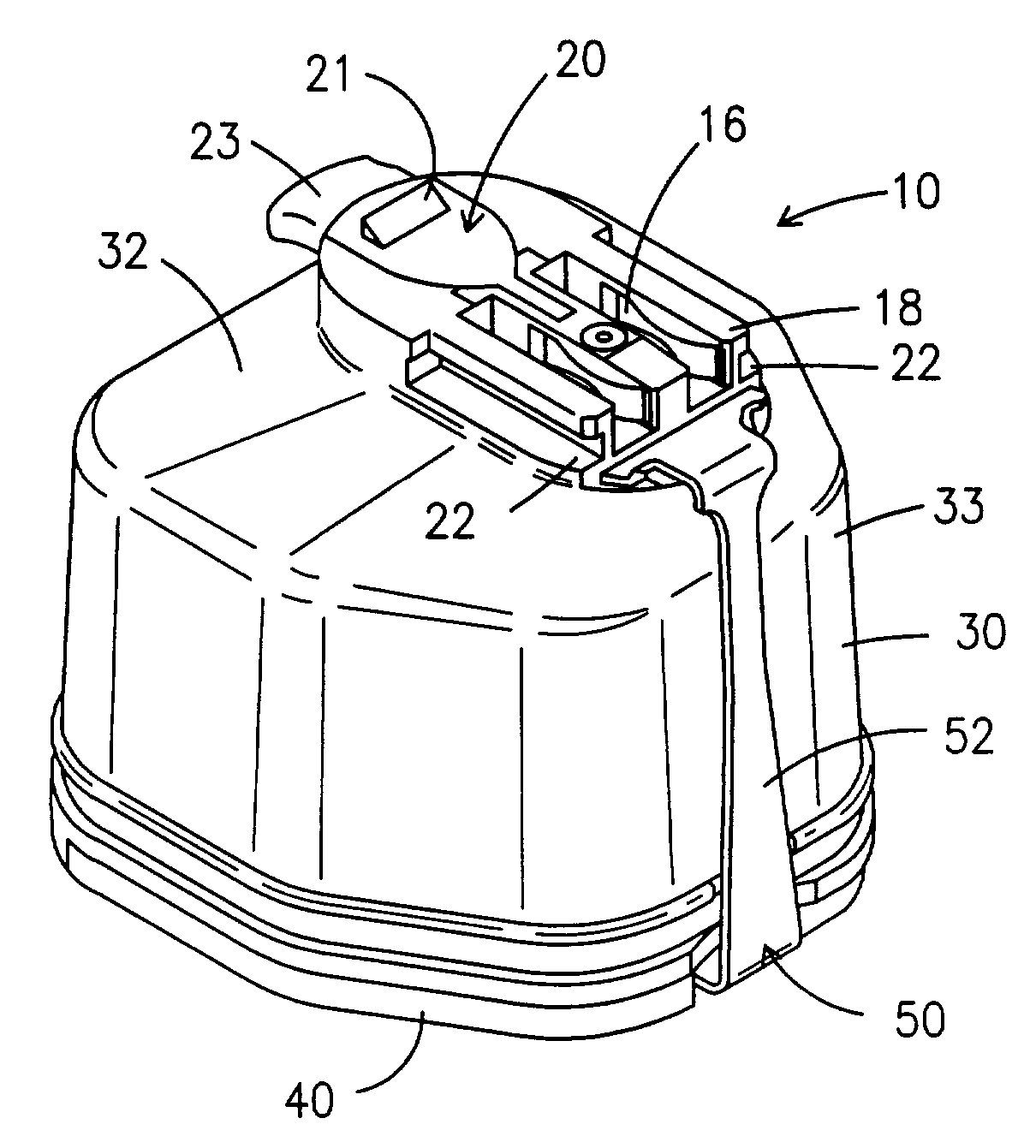
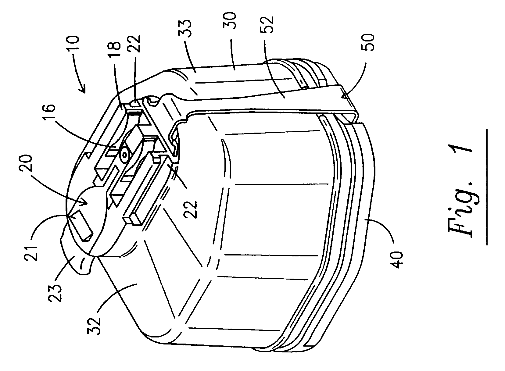
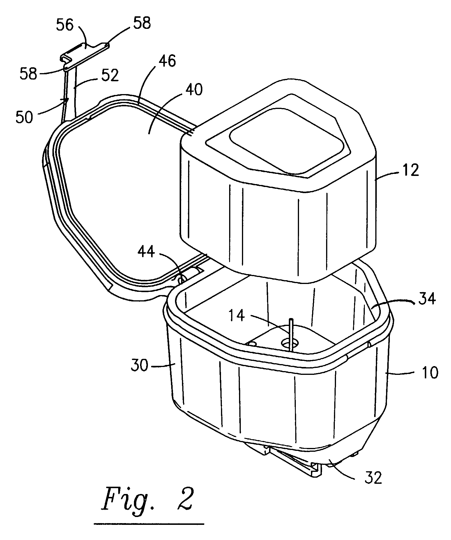
[0024]Referring now to the drawings, there is a shown a sterile transfer container 10 constructed in accordance with the principles of this invention. Container 10 is designed to hermetically enclose battery or battery pack 12 (best seen in FIG. 2) within a sterile environment since the battery itself is not intended to be sterilized when sterile transfer container 10 is used. The interior of sterile transfer container 10 is provided with positive and negative electrical terminals 14 (only one of which is visible in FIG. 2) which are received within complementary sockets (not shown) in battery 12. Terminals 14 are appropriately electrically connected to positive and negative exterior terminals 16 on the exterior of sterile transfer container 10. Container 10 further comprises mounting means 18 and spring loaded, pivotable latching mechanism 20 in order to enable container 10 to be securely attached to a powered surgical instrument 70, best seen in FIG. 7. As best seen in FIG. 9, lat...


PUM

PropertyMeasurementUnit
electrical terminalsaaaaaaaaaa
compressive forceaaaaaaaaaa
shapesaaaaaaaaaa

Abstract

A method and apparatus for enabling the use of a non-sterile battery with a sterile surgical instrument. The sterile transfer container has a tubular body with a closed distal end and an open proximal end. The container is provided with a cover and a locking mechanism for locking the cover to the body. The container is adapted to be attached to a surgical instrument in such a way that the latch assembly is prevented from opening until the container is removed from the instrument.

Description

BACKGROUND OF THE INVENTION[0001]1. Field of the Invention[0002]The invention generally relates to surgical powered instruments. More particularly, the invention relates to battery operated surgical powered instruments. Still more particularly, the invention relates to methods and devices which enable the use of non-sterile rechargeable batteries with sterile surgical instruments.[0003]2. Description of the Prior Art[0004]In order to enable the use of rechargeable non-sterile batteries in sterile surgical instruments, users employ a known “sterile transfer” technique. While possibly known by other names, this technique generally entails the sterilization and use of a sterile battery container to be attached to a sterile powered instrument. The sterilized container is held in a sterile field (by a scrub nurse, for example) and is shielded by a sterile shroud. A non-sterile, charged battery (held by a circulating nurse, for example) is placed into the sterilized container with care so...

Claims


Application Information

Patent Timeline
Patent Type & Authority Patents(United States)
IPC IPC(8): H01M2/10A61B17/00A61B19/00A61B19/02H01M50/202H01M50/244H01M50/247H01M50/262H01M50/271H01M50/296
CPCA61B19/38H01M2/1022H01M2/1094A61B19/026A61B2017/0023A61B2017/00734A61B2019/4868A61B50/30A61B90/40A61B2090/0813Y02E60/10H01M50/24H01M50/247H01M50/202H01M50/296H01M50/244H01M50/262H01M50/271
Inventor BARLEV, B. ALEXECTOR, JR., WALTON LANELIM, JOEPERT R.
Owner LINVATEC
Why Eureka
Try Eureka