
Distributed power supply system with separate SYNC control for controlling remote digital DC/DC converters

a power supply system and remote control technology, applied in the field of dcdc power converters, can solve the problems of large size of the conductor to handle current and the associated isup>2/sup>r power loss

Inactive Publication Date: 2009-03-10
SILICON LAB INC
View PDF31 Cites 23 Cited by
  • Summary
  • Abstract
  • Description
  • Claims
  • Application Information

AI Technical Summary

Problems solved by technology

If this conversion is facilitated at a power supply and then connected to a remote microprocessor on a printed circuit board, the size of the conductor to handle the current and the associated I2R power loss would be large.

Method used


Image

  • Distributed power supply system with separate SYNC control for controlling remote digital DC/DC converters
  • Distributed power supply system with separate SYNC control for controlling remote digital DC/DC converters
  • Distributed power supply system with separate SYNC control for controlling remote digital DC/DC converters

Examples


Embodiment Construction

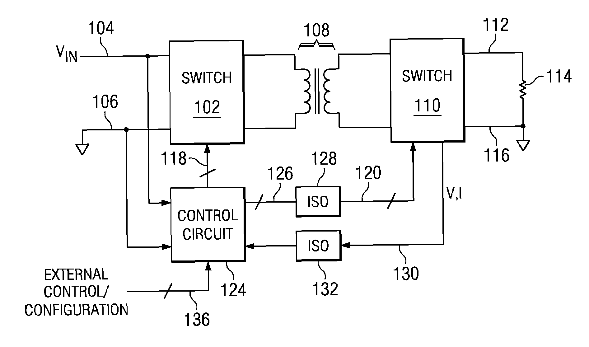
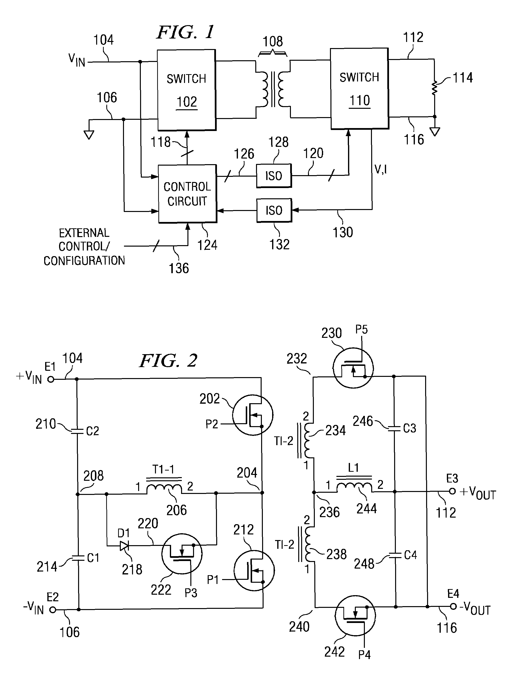
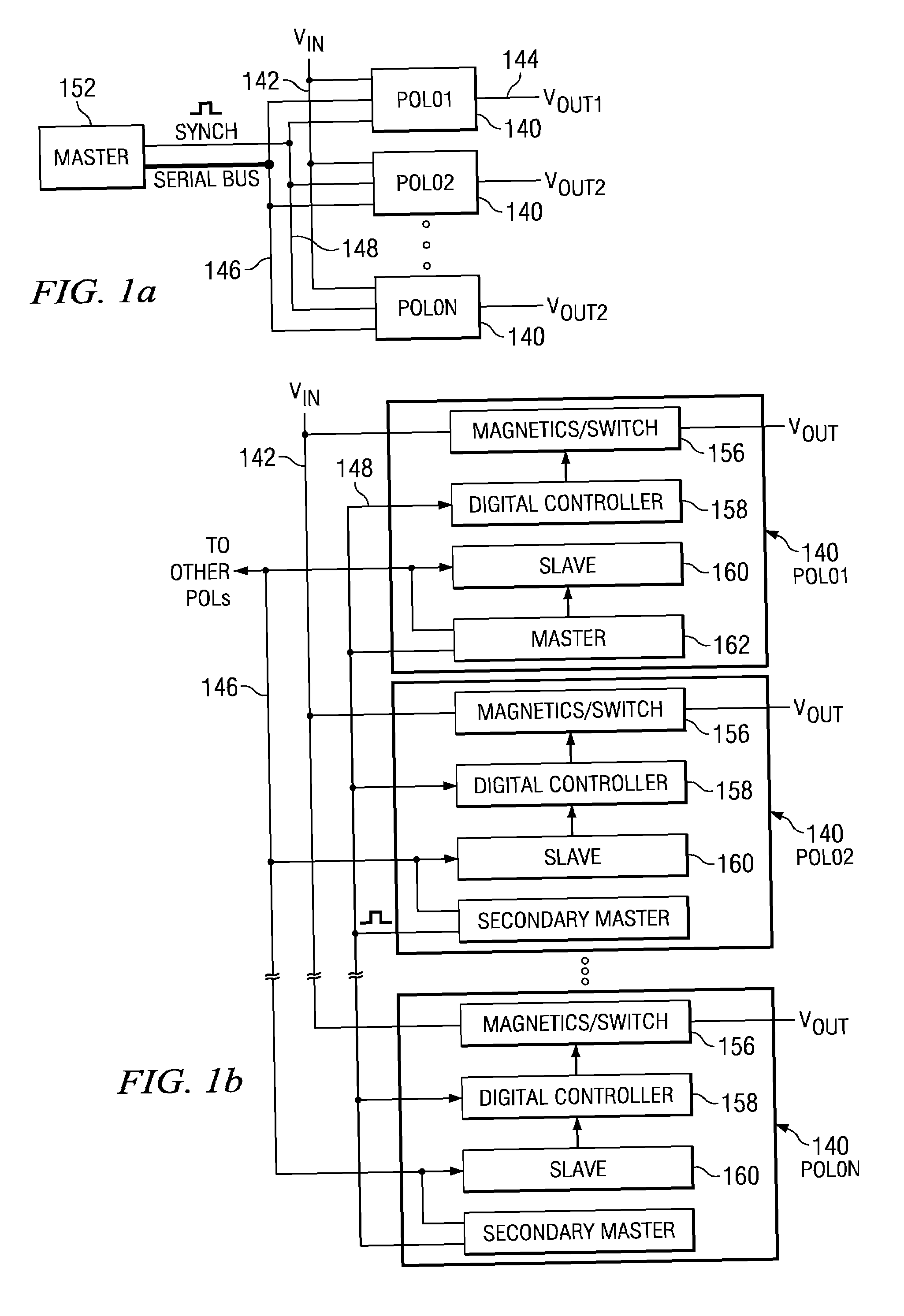
[0077]Referring now to FIG. 1, there is illustrated a top level schematic diagram for the switching power supply of the present embodiment, which in this Fig. is illustrated as a half bridge power supply. The main portion of the power supply comprises a primary switch group 102 that is operable to receive an input voltage on a node 104, this being a DC voltage, and ground on a node 106. The primary switch group 102 is coupled through an isolation transformer 108 to a secondary switch group 110. The secondary switch group 110 is operable to drive an output voltage node 112 that is connected to one terminal of a load 114, the secondary switch group 110 also having a ground connection on a node 116, the load 114 disposed between the node 112 and the node 116. The two switch groups 102 and 110 are operable to operate in conjunction with various pulse inputs on a control bus 118 associated with the primary switch group 102 and with various pulse inputs on a control bus 126 associated wit...


PUM


Abstract

A distributed power system for delivering DC power to a plurality of loads. A plurality of switching DC / DC converter modules are provided, each disposed proximate one of the loads, and each having associated therewith a switching pulse generator for generating switching pulses. A distributed power line distributes input power to each of the modules and a data communication line distributes command data between the modules, each of the modules uniquely addressable over the data communication line. A timing communication line is also provided for distributing timing information to each of the switching pulse generators. A master controller generates commands and communicates them to the data modules over the data communication line, the master controller operable to generate timing information over the timing communication line to each of the modules for controlling the associated switching pulse generator.

Description

CROSS-REFERENCE TO RELATED APPLICATIONS[0001]This application is a Continuation-in-part application of U.S. Ser. No. 11 / 172,358, filed Jun. 30, 2005, entitled “FINITE STATE MACHINE DIGITAL PULSE WIDTH MODULATOR FOR A DIGITALLY CONTROLLED POWER SUPPLY”, which is a Continuation-in-part application of U.S. Ser. No. 11 / 096,597, filed on Mar. 31, 2005, entitled “DIGITAL PWM CONTROLLER” and it is related to U.S. patent application Ser. No. 11 / 096,598, filed Mar. 31, 2005, and entitled “PID BASED CONTROLLER FOR DC-DC CONVERTER WITH POST-PROCESSING FILTERS” and U.S. patent application Ser. No. 11 / 096,853, filed Mar. 31, 2005, and entitled “DIGITAL POWER SUPPLY CONTROLLER WITH VOLTAGE POSITIONING”, both of which are incorporated herein by reference in their entirety and claims priority in Provisional Application No. 60 / 591,463, filed Jul. 27, 2004, which is incorporated herein by reference in its entirety.TECHNICAL FIELD OF THE INVENTION[0002]The present invention pertains in general to DC-D...

Claims


Application Information

Patent Timeline
Patent Type & Authority Patents(United States)
IPC IPC(8): H02J1/10H02J1/00
CPCH02M3/33515H02M3/33576H03K3/356121H03K3/35613H03K7/08H03M1/363
Inventor LEUNG, KAFAILEUNG, KA Y.ALFANO, DONALD E.
Owner SILICON LAB INC
Learn More