Electrical plug-in connector

a plug-in connector and plug-in technology, applied in the direction of electrical apparatus, connection, coupling device connection, etc., can solve the problems of increasing time expenditure, affecting the quality of electrical components, etc., and achieves easy and cheap assembly, the effect of extremely fast and secure assembly

Active Publication Date: 2009-03-17
WEIDMULLER INTERFACE GMBH & CO KG
View PDF9 Cites 12 Cited by
  • Summary
  • Abstract
  • Description
  • Claims
  • Application Information

AI Technical Summary

Benefits of technology

[0010]The present invention was developed to provide a plug connection including plug and socket members such that one can bring about a particularly simple and fast connection with low production costs. The invention first of all provides an electrical plug connection with a plug member provided with a rotatable sleeve, for connection with a socket member that has an interior thread, whereby the sleeve, on its outer circumferential area, that engages the socket member, is provided with at least one deflectable, preferably resiliently deflectable projection that is fashioned in the manner of a part of an external thread turn.
[0014]According to a preferred embodiment, the invention thus creates a plug member with a locking sleeve that can be made in a simple and inexpensive manner, for the fast and uncomplicated connection with a socket member, whereby the socket member can comply with the general industrial standard (for instance, according to the “M” standard, for instance, “M12” or “M8”, or the like). In this case, the socket member is in the known manner provided with an interior thread. This embodiment is particularly preferred.
[0016]The plug member of the present invention, with the shaped sleeve, can, in the axial direction, without any problem, be pushed into a socket member provided with an interior thread, because the projection or the projections can overcome the thread turns of the interior thread by virtue of their resilient capacity, but, at the same time, in each plug insertion state, become locked in a thread turn of the interior thread. After the sleeve has been pushed in axially, the sleeve can still be turned slightly in the way of a screw connection in order to fix a final assembly position. The turn required for this purpose is comparatively minor so that corresponding plug connections can be assembled extremely quickly and securely, specifically, also in poorly accessible installation situations and in case of a relatively tight arrangement of the connections.
[0017]The sleeve can be made easily and cheaply, because the only important thing here is to mold upon the sleeve at least one projection that forms a part of an outer thread turn. The elastic elements furthermore create a permanent vibration safety.
[0018]A development of the basic idea behind the invention, which can also be considered as an independent invention of its own, provides that the sleeve is made as a punch-bending part consisting of sheet metal. This offers the advantage that the locking sleeve need not have to be made as expensive turning part or by means of forming or casting; instead, it can be made by means of simple punching and bending procedures. It is furthermore possible, in this way, to apply this sleeve also upon the actual interior parts as part of a second production step so that these interior parts need not have to be extrusion coated.
[0021]According to another advantageous modification, one can also reduce the time required for undoing the connection when compared to known connections, specifically, when the projections are not so arranged on the plug part or socket part that they engage the thread turn of the corresponding thread which is last in the axial plug-in directions, but instead, engage one of the first thread turns in the axial plug-in direction, for example, they engage in one of the first four, in particular, the second thread turn, because now one needs only a number of thread turns that would correspond to the number of rotation motions needed for separation. The plug part or socket part can be designed for assembly upon a housing or for connection to a cable.

Problems solved by technology

Connections on distributors used in automation technology are often arranged relatively closely to each other, something that also adds to the time expenditure and makes the connection operation relatively laborious.
But there is one disadvantage here: Designs used in the past necessitate expensive production and processing both of the sleeve of the plug part as well processing of the socket member, since currently known designs are based on the idea that [they] contain either bayonet-like connection possibilities or that both the sleeve of the plug part as well as the socket member are provided with unthreaded areas that extend in the axial direction, which facilitate an axial assembly or plugging-in, without any need for a turn and which only at the very last moment permit axial retention by turning.
In the latter variant, a connection is made to an interior thread which is not provided with the axially free areas; in that case, one can furthermore not save any time when compared to the known screw connections.

Method used


Image

  • Electrical plug-in connector
  • Electrical plug-in connector
  • Electrical plug-in connector

Examples


Embodiment Construction

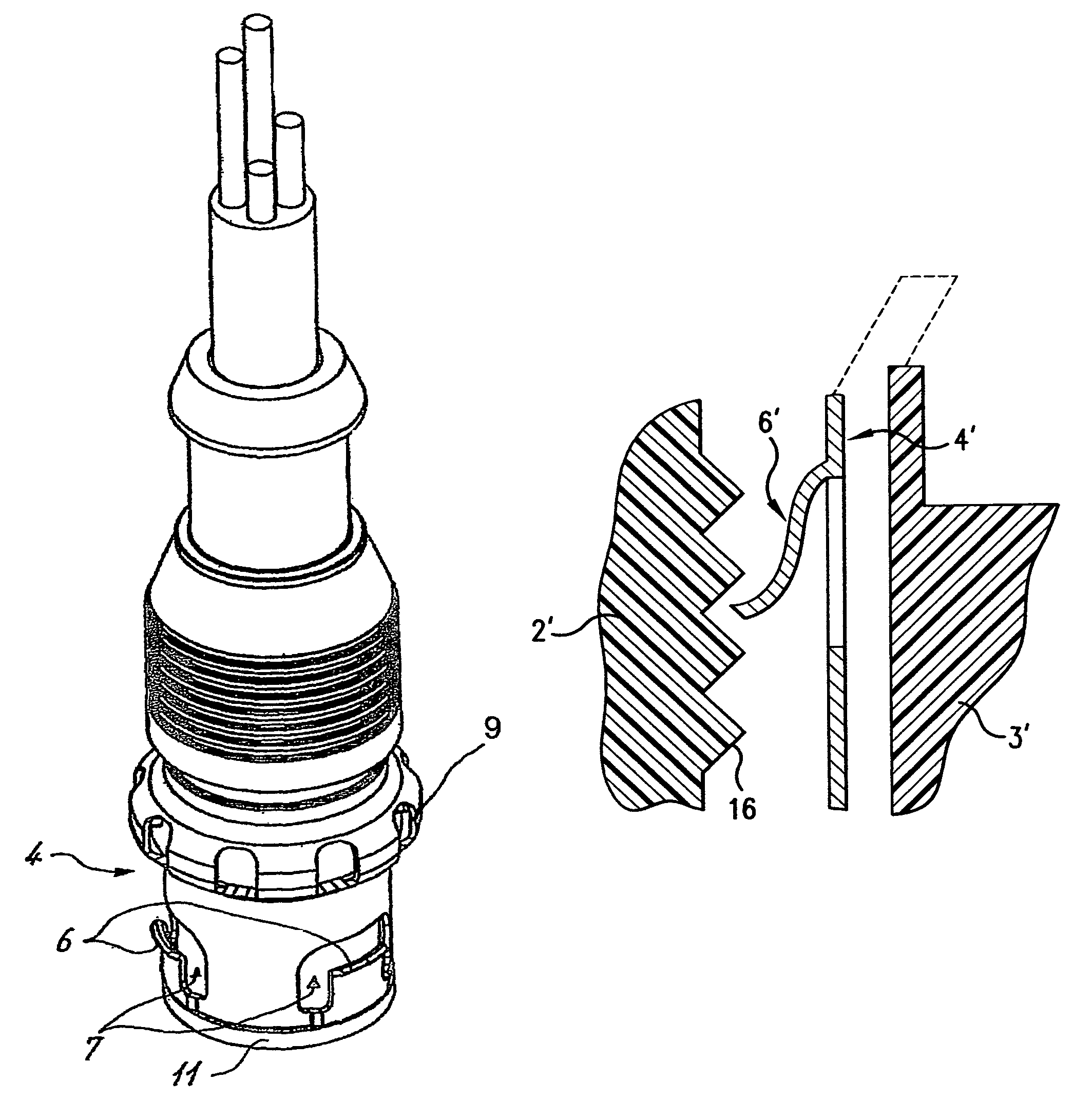
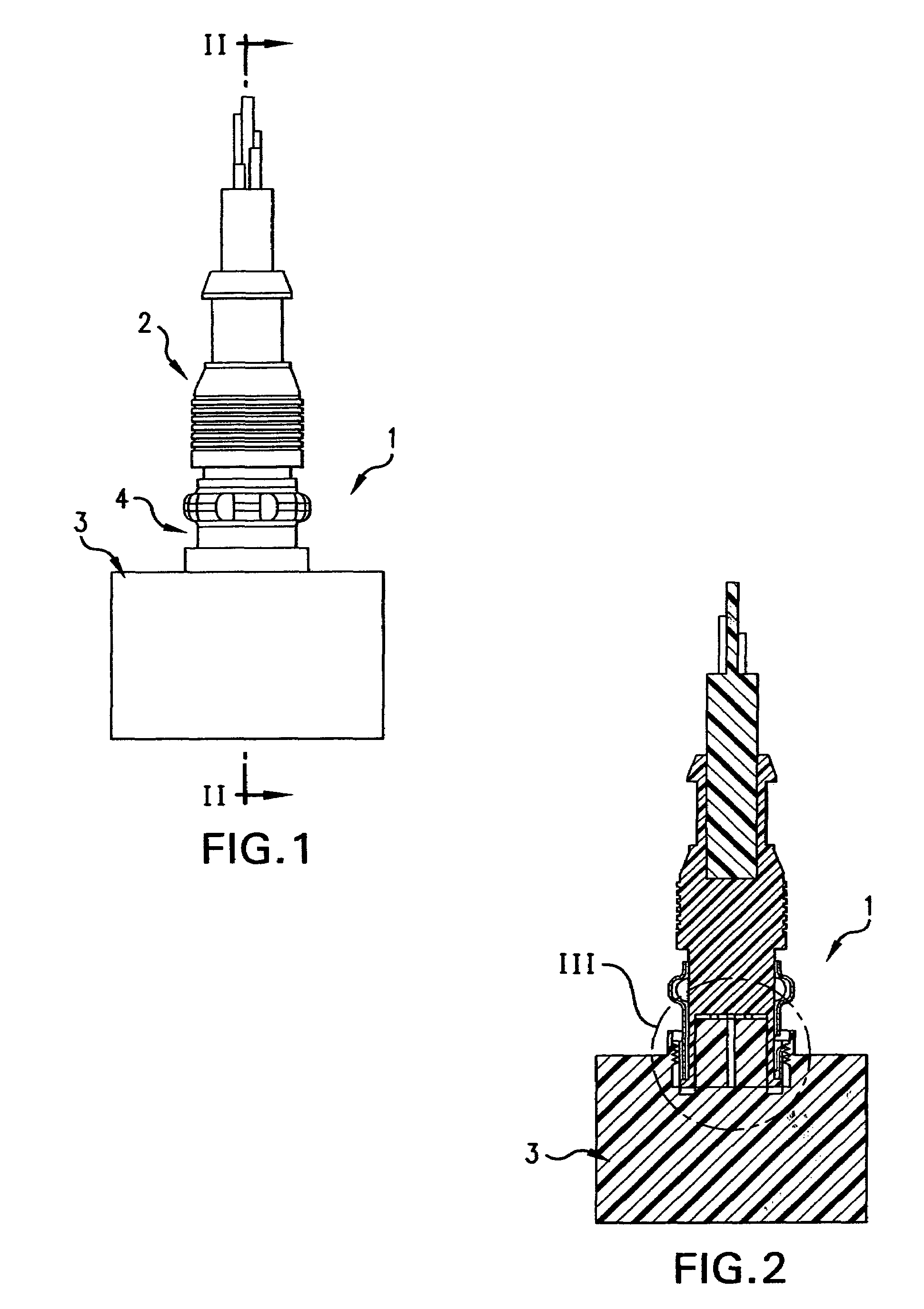
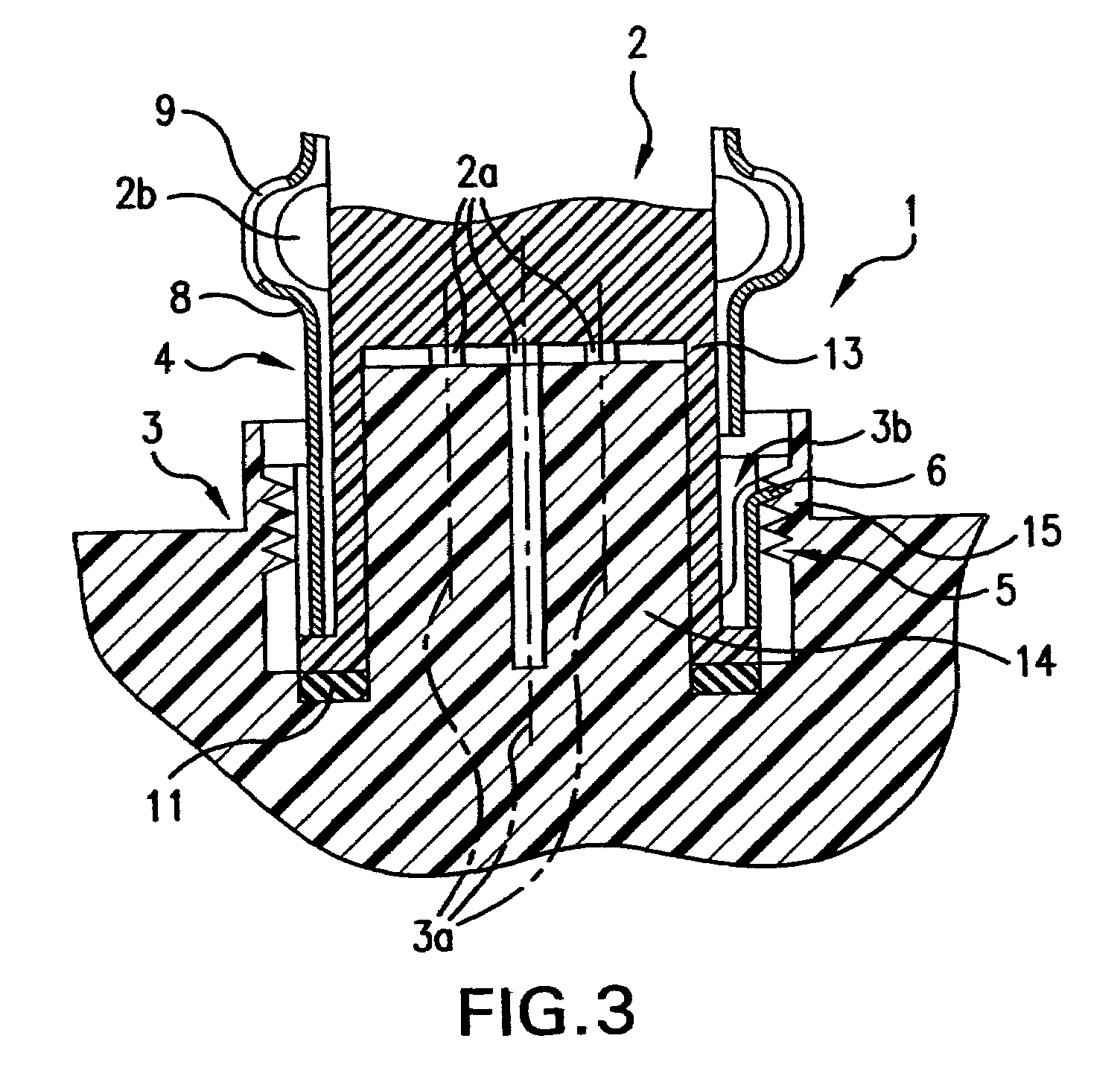
[0032]In FIGS. 1 to 3, the reference symbol 1 generally designates a plug connection arrangement which comprises a plug member 2 and a socket member 3 which can be plugged together linearly in the axial direction, as oriented and guided by guide means 20 (FIG. 4). The plug and socket members are equipped with corresponding first and second contacts 2a, 3a that in this case are made as pins 2a and corresponding sockets 3a. Plug member 2 has a cylindrical interior body 13 preferably consisting of an electrically-insulating synthetic plastic material, with the first contacts 2a, and the socket member 3 also has an interior body 14 consisting of electrically-insulating synthetic plastic material, with the second contacts 3a, whereby, in this case, the interior body of the socket 3 can be plugged, in its axial terminal area, into the internal body of plug member 2.

[0033]The plug member is equipped with a concentrically mounted locking sleeve 4 that is connected against longitudinal displ...


PUM


Abstract

A quick-fastening plug and socket arrangement includes a locking sleeve arranged concentrically between the plug and the circular socket opening within which the plug is axially inserted, which locking sleeve includes a resilient projection that is radially biased outwardly into locking engagement with screw threads carried by the inner circumferential surface of the socket opening. Alternatively, the projecting portion is biased radially inwardly for locking engagement with screw threads carried by the outer circumferential surface of the plug member. The sleeve is connected against longitudinal displacement relative to one of the plug and socket members, which sleeve is rotatable relative to the associated plug and socket member, thereby to release the plug for removal from the socket opening.

Description

BACKGROUND OF THE INVENTION[0001]1. Field of the Invention[0002]A quick-fastening plug and socket arrangement includes a locking sleeve arranged concentrically between the plug and the circular socket opening within which the plug is axially inserted, which locking sleeve includes a resilient projection that is radially biased outwardly into locking engagement with screw threads carried by the inner circumferential surface of the socket opening. The locking sleeve is connected against longitudinal displacement relative to an associated one of the plug and socket members, said sleeve being rotatable relative to the associated plug and socket member, thereby to release the plug for removal from the socket opening.[0003]2. Description of Related Art[0004]It is well known in the patented prior art to provide various plug and socket arrangements, as evidenced, for example, by the prior U.S. patents to Bury U.S. Pat. No. 7,059,891 and Schumacher et al U.S. Pat. No. 7,207,824, among others...

Claims


Application Information

Patent Timeline
Patent Type & Authority Patents(United States)
IPC IPC(8): H01R4/38
CPCH01R13/622H01R13/6277
Inventor HOLTERHOFF, KLAUSSALOMON, THOMASMACKEY, DENNIS C.
Owner WEIDMULLER INTERFACE GMBH & CO KG
Why Eureka
Try Eureka