
Light-weight wind driven generator

A wind turbine, lightweight technology, applied to wind turbines, wind turbine combinations, wind turbines at right angles to the wind direction, etc. problem, to achieve the effect of simple and fast connection, high wind energy utilization, and low resistance

Inactive Publication Date: 2012-05-02
李胜然
View PDF5 Cites 1 Cited by
  • Summary
  • Abstract
  • Description
  • Claims
  • Application Information

AI Technical Summary

Problems solved by technology

[0002] Existing wind power generators generally include a hollow central shaft, a motor casing rotatably fitted on the central shaft, a permanent magnet fixed to the inner wall of the motor casing, and a motor casing located in the cavity and relatively centered. The shaft is fixed to the coil and the fan body. The overall weight of the generator is large. When the wind is small, it cannot start. When the wind speed is high, it will automatically cut off the output and stop working; the structure of the fan blade is unreasonable, and the utilization rate of wind energy is low

Method used


Image

  • Light-weight wind driven generator
  • Light-weight wind driven generator
  • Light-weight wind driven generator

Examples


Embodiment Construction

[0022] Below in conjunction with embodiment and accompanying drawing, the present invention will be further described:

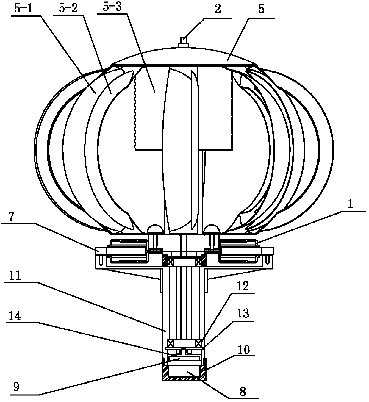
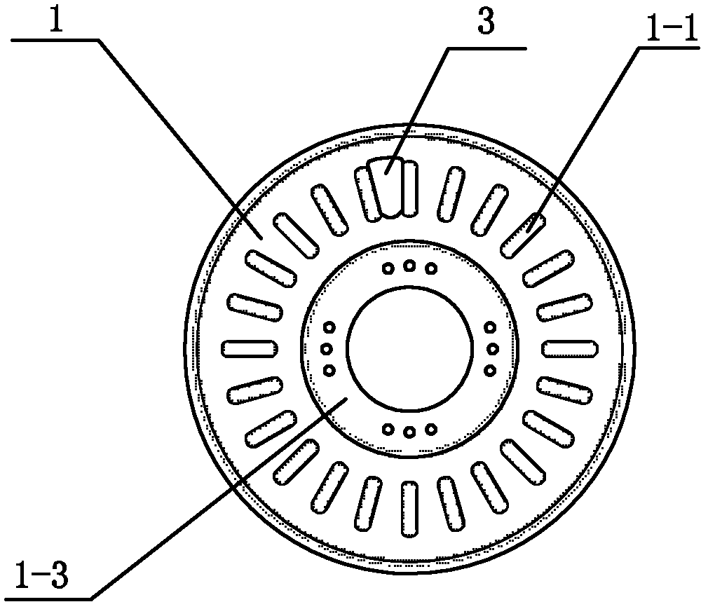
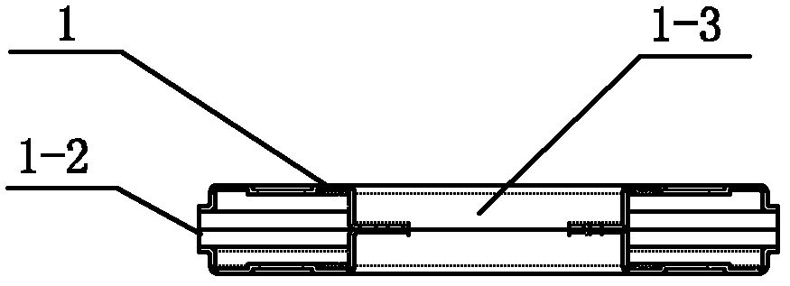
[0023] refer to figure 1 and figure 2 , a light-duty wind power generator, including a motor housing 1, a central shaft 2 that passes through the motor housing 1 and can rotate relative to the motor housing, a permanent magnet 3 and a coil 4 placed in the motor housing, and is sleeved on the The fan blade body 5 on the central axis has protrusions 1-1 arranged at equidistant intervals along the circumferential direction in the housing 1, and the permanent magnet 3 is clamped in the concave area between two adjacent protrusions; the coil 4 as a whole is Annular, provided with an insulating inner fixing ring 6 and an outer fixing ring 7, the housing 1 has a gap 1-2 exposed for the outer fixing ring and a boss 1-3 extending into the inner fixing ring, the housing of this embodiment 1. It consists of two shell units that are fastened up and down; the motor sh...


PUM

PropertyMeasurementUnit
Thicknessaaaaaaaaaa

Abstract

The invention provides a light-weight wind driven generator which comprises a motor shell, a middle shaft, a permanent magnet, a coil and a fan blade body, wherein the middle shaft penetrates through the motor shell and can rotate relative to the motor shell; the permanent magnet and the coil are arranged in the motor shell; the fan blade body is sleeved on the middle shaft; the shell is internally provided with protrusions which are arranged at equal intervals in the circumferential direction; the permanent magnet is clamped in a concave area between two adjacent protrusions; the coil is annular integrally, and is provided with an insulating internal fixed ring and an insulating external fixed ring; the shell is provided with a notch for uncovering the external fixed ring and a boss which extends into the internal fixed ring; the motor shell and a motor mounting seat are fixedly connected; the motor mounting seat is internally provided with the permanent magnet; and the lower end of the middle shaft is fixedly connected with a permanent magnet with the same opposite-face polarity as the permanent magnet in the motor mounting seat. The wind driven generator provided by the invention has the beneficial effects that the connection mode of the permanent magnet and the shell is simple and quick; the shell can be manufactured to be very thin, and has a light and handy structure; and through the permanents with the same opposite-face polarity, the middle shaft and the fan blade body are suspended relative to the motor mounting seat, and the resistance of the generator is reduced.

Description

technical field [0001] The invention relates to the technical field of wind power generation, in particular to a light wind power generator. Background technique [0002] Existing wind power generators generally include a hollow central shaft, a motor casing rotatably fitted on the central shaft, a permanent magnet fixed to the inner wall of the motor casing, and a motor casing located in the cavity and relatively centered. The shaft is fixed to the coil and the fan body. The overall weight of the generator is large. When the wind is small, it cannot start. When the wind speed is high, it will automatically cut off the output and stop working; the structure of the blade body is unreasonable, and the utilization rate of wind energy is low. Contents of the invention [0003] The object of the present invention is to provide a light wind power generator with light structure, high utilization rate of wind energy and multiple output modes. [0004] Object of the invention of ...

Claims


Application Information

Patent Timeline
IPC IPC(8): F03D9/00F03D3/06H02K5/04H02K3/04H02K3/28
CPCY02E10/74Y02P70/50
Inventor 李胜然
Owner 李胜然
Learn More