Folding mechanism for a conveyor device

A technology for conveying devices and conveyors, applied in the direction of conveyors, conveyor objects, transportation and packaging, etc., to achieve the effects of smooth operation, simple installation, and reliable absorption

Active Publication Date: 2018-01-26
KLEEMANN
View PDF10 Cites 1 Cited by
  • Summary
  • Abstract
  • Description
  • Claims
  • Application Information

AI Technical Summary

Problems solved by technology

[0006] A disadvantage of the folding mechanism disclosed above is additionally that the joints are arranged in such a way that there is always a combination of a rotational movement of the conveyor belt about its longitudinal axis and a simultaneous folding movement of the conveyor belt relative to the material processing device

Method used


Image

  • Folding mechanism for a conveyor device
  • Folding mechanism for a conveyor device
  • Folding mechanism for a conveyor device

Examples


Embodiment Construction

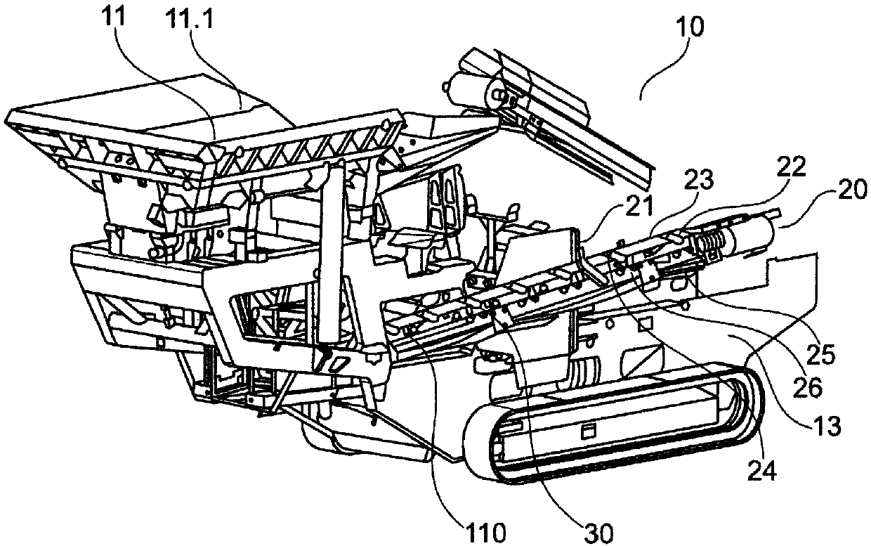
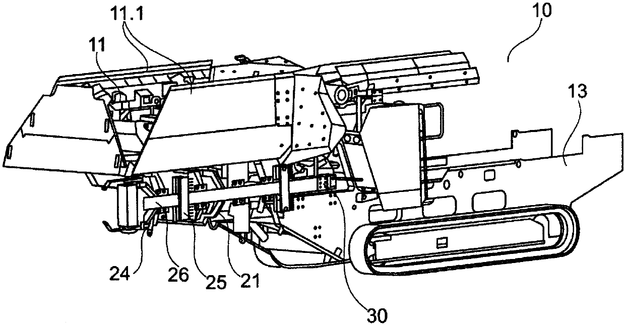
[0030] figure 1 The movable material processing apparatus is shown in an operating position. The material processing device 10 is used for crushing excavated material, which is fed to the material processing device 10 through a feed hopper 11 having a funnel wall 11.1. Material is removed by means of a conveyor arrangement 20 . The conveyor arrangement 20 is connected to the chassis 13 of the mobile material processing arrangement 10 by a base portion 110 . The transport section 24 of the conveyor arrangement 20 is connected to the base section 110 by a joint section 30 . The belt 23 of the conveyor device 20 is guided along the supporting profile 26 of the transport section 24 . For this purpose, a belt 23 is mounted on rollers 22 and is held transversely by transverse belt guides 21 and is situated on the bottom side of the conveyor arrangement 20 by bottom belt guides 25 .

[0031] The base part 110 is connected to the chassis 13 so as to move in such a way that the inc...


PUM


Abstract

The invention relates to a conveyor device (20) for a material machining device (10), comprising a base portion (110) and a transport portion (24). The base portion (110) is designed for coupling to the material machining device (10) and is connected to the transport portion (24) via a joint portion (30) such that the transport portion (24) is rotatable or pivotal and can be folded inwards about alongitudinal axis between an operating position and a transport position on at least one part of the adjustment path of the transport portion (24) by means of a first and a second rotary joint (36, 35). The joint portion (30) has a first and a second connection element (40, 80) and a joint central part (50); the first connection element (40) is equipped for directly or indirectly coupling to thematerial machining device (10), and the second connection element (80) is equipped for directly or indirectly coupling to the transport portion (24); and the connection elements (40, 80) and the jointcentral part (50) are coupled by means of the two rotary joints (35, 36). The conveyor device (20) can be mounted and used on both sides of the material machining device (10) by means of the joint portion (30).

Description

technical field [0001] The invention relates to a conveyor device for a material processing plant, having a base part and a transport part, wherein the base part is realized for coupling to the material processing plant and is connected to the transport part by a joint part in such a way that the transport part It is rotatable or pivotable about a longitudinal axis between an operating position and a delivery position along at least a portion of the adjustment path of the transport section via the first and second swivel joints, and can be folded in. Background technique [0002] Document EP 1 628 896 B1 discloses a foldable conveyor belt attached to the side of a movable chassis. It includes three component areas. The base area is firmly attached to the chassis. The middle region is pivotally connected to the base region, and the end regions are mounted to pivot on the middle region. Two-part braces connect the chassis to the end sections. The two-part parts of the supp...

Claims


Application Information

Patent Timeline
Patent Type & Authority Applications(China)
IPC IPC(8): B65G21/12B65G41/00
CPCB65G41/002B65G2201/04B65G21/12
Inventor C·韦勒F·弗兰岑
Owner KLEEMANN
Why Eureka
Try Eureka