Mounting unit and method for mounting a mounting rail to a mounting plate for a switch cabinet

a technology for mounting units and switch cabinets, which is applied in the direction of electrical apparatus construction details, coupling device connections, and coupling device details, etc., can solve the problems of shortening the throughput time in the production of switch cabinets, and achieves fast, simple and secure mounting and increasing security

Active Publication Date: 2017-02-28
KRONES AG
View PDF17 Cites 1 Cited by
  • Summary
  • Abstract
  • Description
  • Claims
  • Application Information

AI Technical Summary

Benefits of technology

[0008]Therefore, it is the object of the present invention to provide a mounting unit and a method for mounting a mounting rail on a mounting plate for a switch cabinet with which the above-mentioned problems can be solved. In particular, a mounting unit and a method for mounting a mounting rail on a mounting plate for a switch board should be provided with which a simple and fast connection between the mounting rail and the mounting plate can be produced. For example, it shall not be necessary, to dismount electrical devices for fastening the mounting rail or to spare space for electrical devices.

Problems solved by technology

This causes a shorter throughput time in the production of the switch cabinet.

Method used


Image

  • Mounting unit and method for mounting a mounting rail to a mounting plate for a switch cabinet
  • Mounting unit and method for mounting a mounting rail to a mounting plate for a switch cabinet
  • Mounting unit and method for mounting a mounting rail to a mounting plate for a switch cabinet

Examples


Embodiment Construction

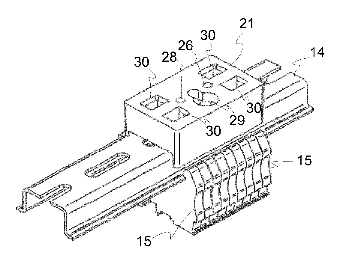
[0041]FIG. 1 shows a switch cabinet 1 with a left door 10, a right door 11, a mounting plate 12, a line conduit 13, and a mounting rail 14 on which electrical devices 15 are mounted, which are schematically shown. The mounting rail 14 can be, for example, a cap rail, a C-rail, etc. The electrical devices 15 comprise, for example, terminal blocks, circuit breakers, motor protection switches, relays, contactors, etc. The switch cabinet 1 can thus be a part of the electrical distribution of a building. The switch cabinet 1 can, however, also comprise electrical devices 15 which act, for example, for the control of a machine, in particular of a container treatment plant, which is not shown and which is for treating of containers for receiving a product, a grinding machine, a ventilation plant, an assembly line, etc.

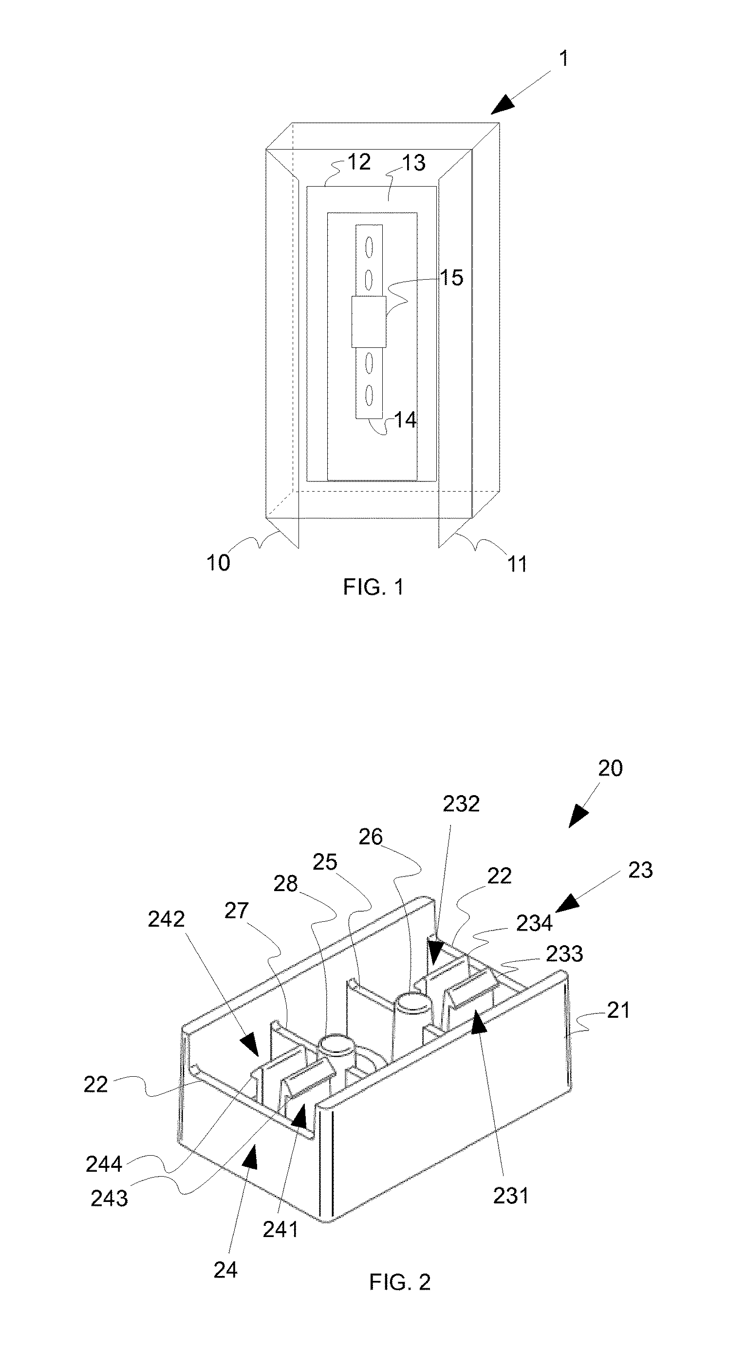
[0042]FIG. 2 shows a mounting unit 20 which is used in the switch cabinet 1 in FIG. 1 for mounting the mounting rail 14 on the mounting plate 12.

[0043]The mounting unit 20 ha...


PUM


Abstract

A mounting unit and a method are provided for mounting a mounting rail to a mounting plate for a switch cabinet. The mounting unit acts for mounting a mounting rail for electrical devices on a mounting plate for a switch cabinet and comprises a coupling element for coupling the mounting unit by a form closure with the mounting rail.

Description

CROSS-REFERENCE TO RELATED APPLICATIONS[0001]This application is a National Stage application of International Application No. PCT / EP2013 / 053311, filed on Feb. 20, 2013, which claims priority of German patent application number 10 2012 102 170.8, filed on Mar. 15, 2012, both of which are incorporated herein by reference in their entireties.BACKGROUND OF THE INVENTION[0002]Field of the Invention[0003]The invention relates to a mounting unit and a method for mounting a mounting rail to a mounting plate for a switch cabinet.[0004]Description of the Prior Art[0005]Conventionally, electrical devices placed in a switch cabinet are used for an electrical control of machines. The electrical devices in the switch cabinet are usually mounted on mounting rails like for example cap rails or C-rails. Herein, the electrical devices, in particular, terminal blocks, relays, contactors, etc., shall be clamped on the mounting rail, initially. Thereafter, the cap rails are mounted on a mounting plate ...

Claims


Application Information

Patent Timeline
Patent Type & Authority Patents(United States)
IPC IPC(8): H02B1/052H05K7/18H01R9/26H02B1/20H02B1/04H01R13/74
CPCH02B1/052H05K7/183H01R9/2608H01R13/741H02B1/04H02B1/205
Inventor PETER, MICHAEL
Owner KRONES AG
Why Eureka
Try Eureka