Orthotic brace

a knee joint and orthopaedic technology, applied in the field of orthopaedic braces, can solve the problems of decreased knee joint capability and integrity, increased strain, and increased possibility of tendonitis, sprains,

Active Publication Date: 2009-03-24
JRI SHOCKS LLC
View PDF236 Cites 51 Cited by
  • Summary
  • Abstract
  • Description
  • Claims
  • Application Information

AI Technical Summary

Problems solved by technology

Even minimal amounts of pain and swelling are enough to alter the normal quadriceps-hamstring relationship, which decreases the knee joint's capability and integrity.
1. The person will be unable to perform at his or her previous physical level. Decreased performance levels will be evident and the possibility of tendonitis, sprains, and strains is increased.
2. The VMO / Quadriceps group will not operate at a level sufficient enough to prevent sudden buckling (collapsing) of the knee, risking injury to internal and external knee components.
3. The hamstring muscle group will not work at an efficient level to prevent hyperextension of the knee, risking injury through tearing internal knee components.
Most of the described injuries will cause loss of time from work and may require physical therapy and / or surgical intervention.
These costs do not include any durable medical equipment, which includes functional knee bracing, or lost time at work.
However, females have been shown to have a greater chance of injury than their male counterparts by two to eight times. With the military looking at expanding the role of females in combat and non-combat situations, the potential rise in lost time of service may increase in the future.
Though many braces attempt to minimize the potential of a hyperextension injury, these braces do not minimize the chance of a buckling injury.
Commercially available passive knee braces do not adequately address the issues of trying to control swelling and pain during gait activities.

Method used


Image

  • Orthotic brace
  • Orthotic brace
  • Orthotic brace

Examples


Embodiment Construction

[0065]For the purposes of promoting an understanding of the principles of the invention, reference will now be made to the embodiments illustrated in the drawings and specific language will be used to describe the same. It will nevertheless be understood that no limitation of the scope of the invention is thereby intended, such alterations and further modifications in the illustrated device, and such further applications of the principles of the invention as illustrated therein being contemplated as would normally occur to one skilled in the art to which the invention relates. It is further understood that there is no single element, feature, aspect, concern, or advantage that is a requirement for every embodiment of the present invention, or for any embodiment of the present. Every use of the term “invention” herein refers to a specific embodiment, but not to all embodiments. Some of the drawings may be described as being drawn to scale. The use of scaled drawings is to show an exa...


PUM


Abstract

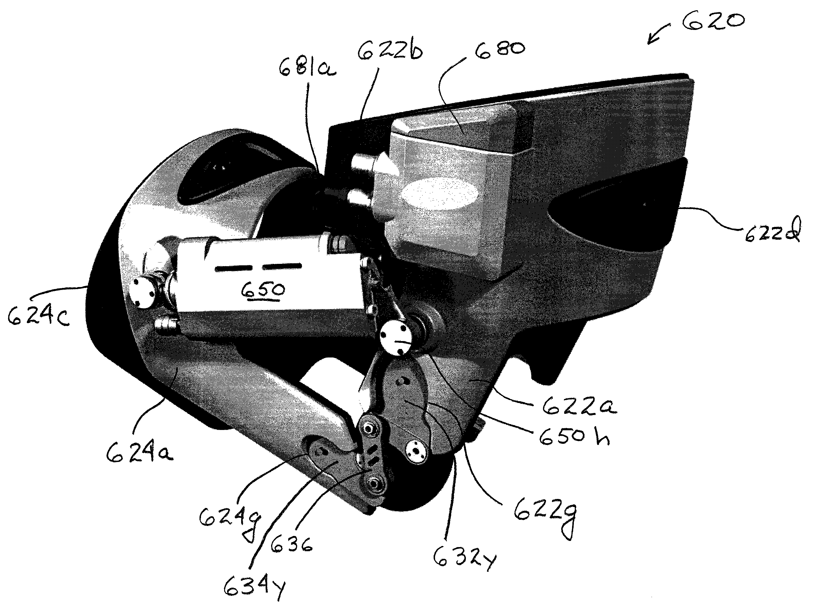
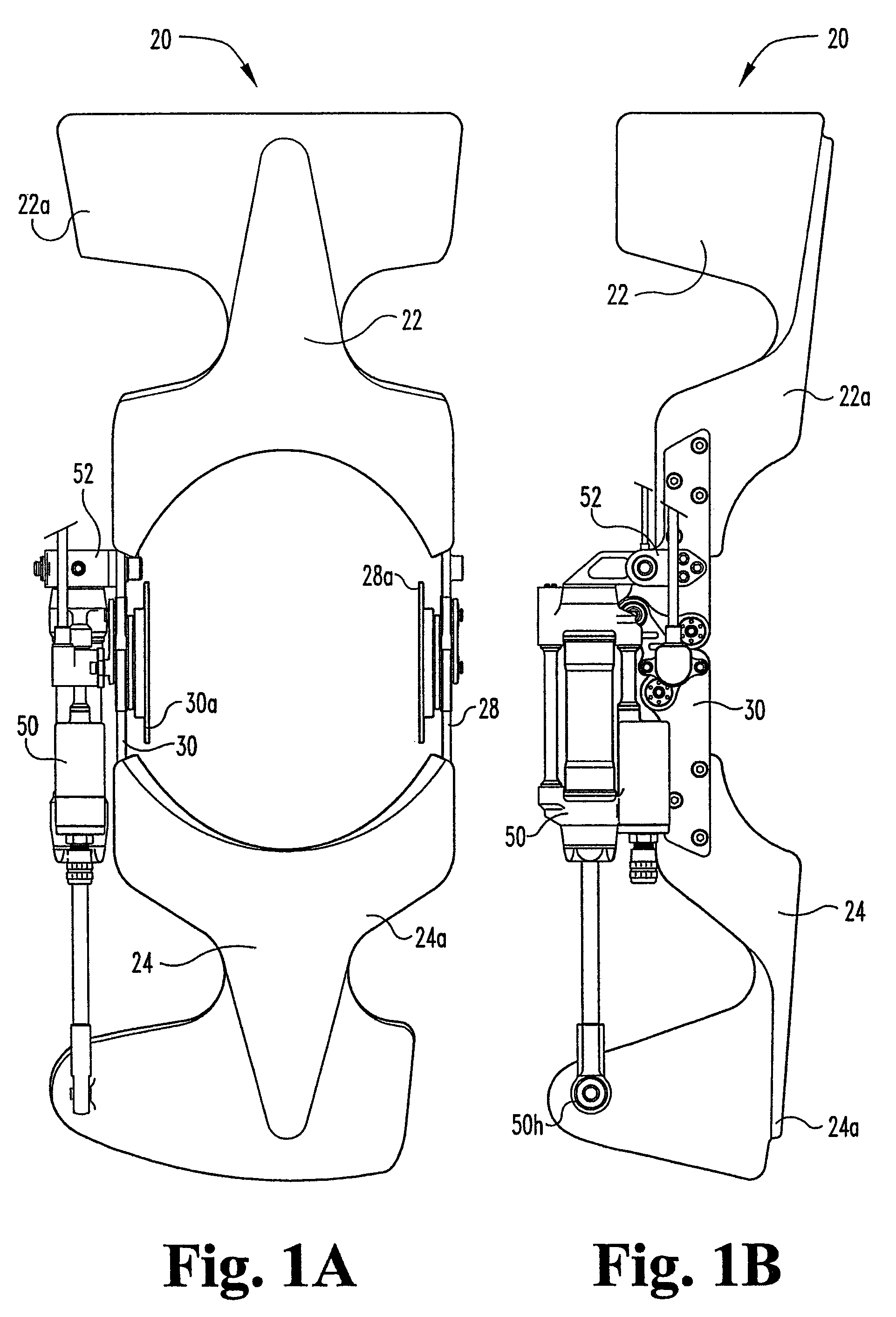
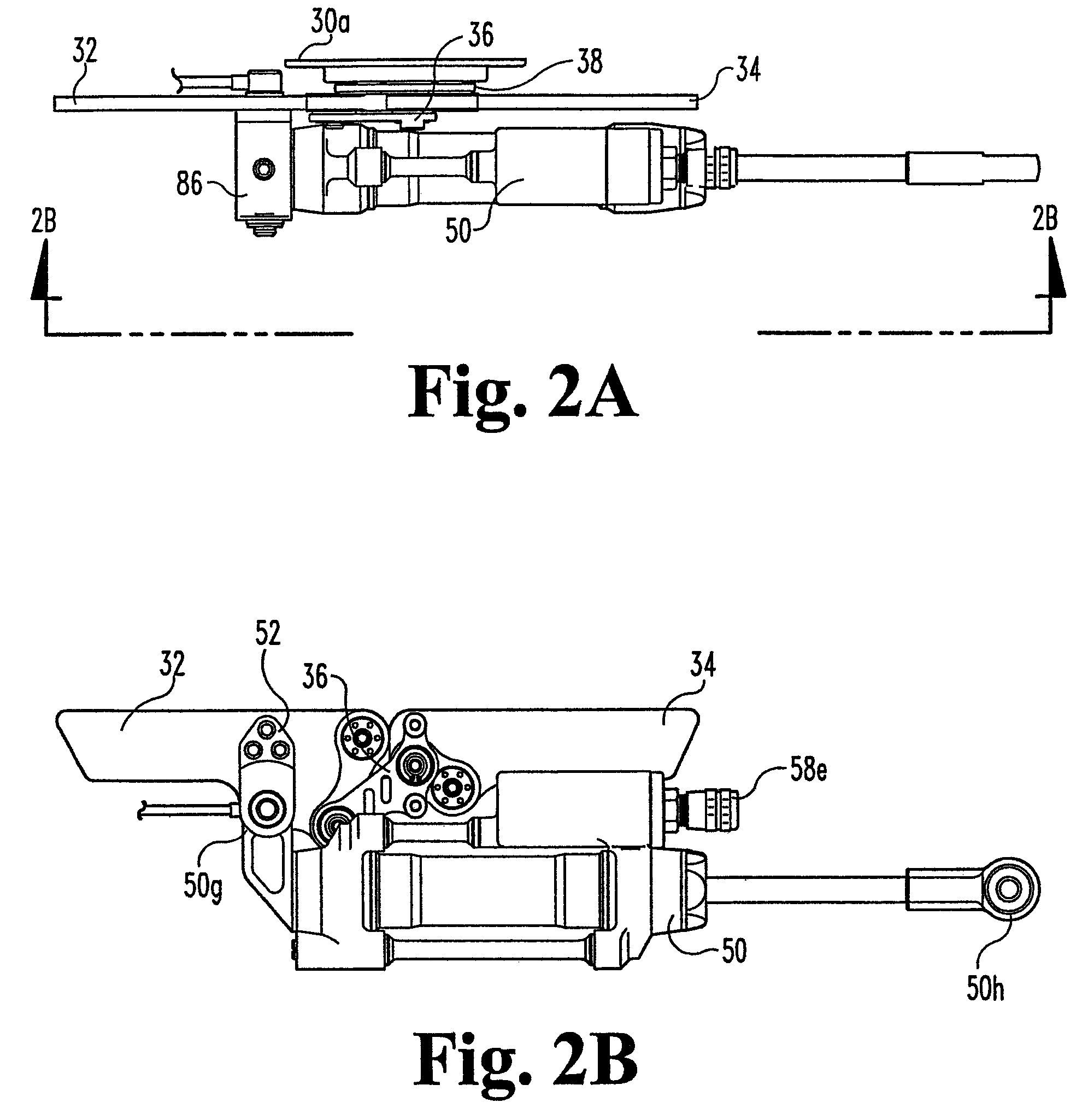
An articulated assembly for replacing or supporting a joint between two limbs of an animal. In one embodiment, the present invention relates to an orthotic knee brace for supporting a human knee. The knee brace includes an upper leg attachment and a lower leg attachment which are interconnected with a hinge and a damper. In some embodiments, the hinge is a four bar linkage and the damper is a hydraulic shock absorber.

Description

CROSS REFERENCE TO RELATED APPLICATIONS[0001]This application claims priority to U.S. Provisional Patent Application Ser. No. 60 / 697,426, filed Jul. 8, 2005; U.S. Provisional Patent Application Ser. No. 60 / 697,513, filed Jul. 8, 2005; and U.S. Provisional Patent Application Ser. No. 60 / 698,157, filed Jul. 11, 2005, all of which are incorporated herein by reference.FIELD OF THE INVENTION[0002]Various embodiments of the present invention pertain to methods and apparatus for supporting or replacing a joint of an animal, and in particular, for providing support for a human knee or for replacing a human knee.BACKGROUND OF THE INVENTION[0003]The knee joint is a uni-axial hinge joint. The knee moves in a flexion (bending of the knee) and extension (straightening of the knee) direction. The three major bones that form the knee joint are: the femur (thigh bone), the tibia (shin bone), and the patella (kneecap). The prime muscle movers of the knee joint are the quadriceps muscles (on top of t...

Claims


Application Information

Patent Timeline
Patent Type & Authority Patents(United States)
IPC IPC(8): A61F5/00
CPCA61F5/0123A63B21/1449A61F2005/0144A61F2005/0146A61F2005/0169A63B21/0081A63B21/0083A63B23/0494A63B2208/14A63B21/008A63B21/4025
Inventor RYAN, JEFF
Owner JRI SHOCKS LLC
Why Eureka
Try Eureka