
Ankle Foot Orthosis

a technology for ankles and feet, applied in the field of orthotics, can solve the problems of foot, heel, foot, and especially the heel, and can swing in the support plate, and can cause chafing and soreness,

Inactive Publication Date: 2009-08-06
YAAD ADVANCED ORTHOPEDICS
View PDF9 Cites 44 Cited by
  • Summary
  • Abstract
  • Description
  • Claims
  • Application Information

AI Technical Summary

Benefits of technology

[0002]The present invention, in some embodiments thereof, relates to ortho

Problems solved by technology

As a result, the foot may catch on low lying debris, rocks or even an edge of a pavement stone, causing the person to trip and fall.
A fall, particularly in an osteoporotic older person, can result in life-threatening bone fractures, immobility, and, due to the resultant sedentary life style, an early demise.
With the movement transferred to the foot, rather than the above-noted joints, the foot, and particularly the heel, may swing in the support plate and tend to become chaffed and sore.
Such limitation of motion may reduce the ability of the foot to act as a shock absorber during heel-strike through foot flat portions of the gait cycle.
With the decrease in foot shock absorption, the shock forces of heel strike are translated up the leg to the knee and hip joints, leading to osteoarthritis, pain, and possible limitation of range of motion in the knee and hip.
Additionally, the shock forces absorbed may be translated to the lower back, resulting in lower back pain and possibly disc herniation, particularly in the lumbar spinal area.
If the foot plate maintains an intrinsic rigidity during gait, the midtarsal area of the foot may be forced to passively supinate against the rigid plate and / or rearfoot, creating undue stress on the midtarsal joint which can result in pain, arthritis and limitation of motion in the midtarsal joint.

Method used


Image

  • Ankle Foot Orthosis
  • Ankle Foot Orthosis
  • Ankle Foot Orthosis

Examples


Embodiment Construction

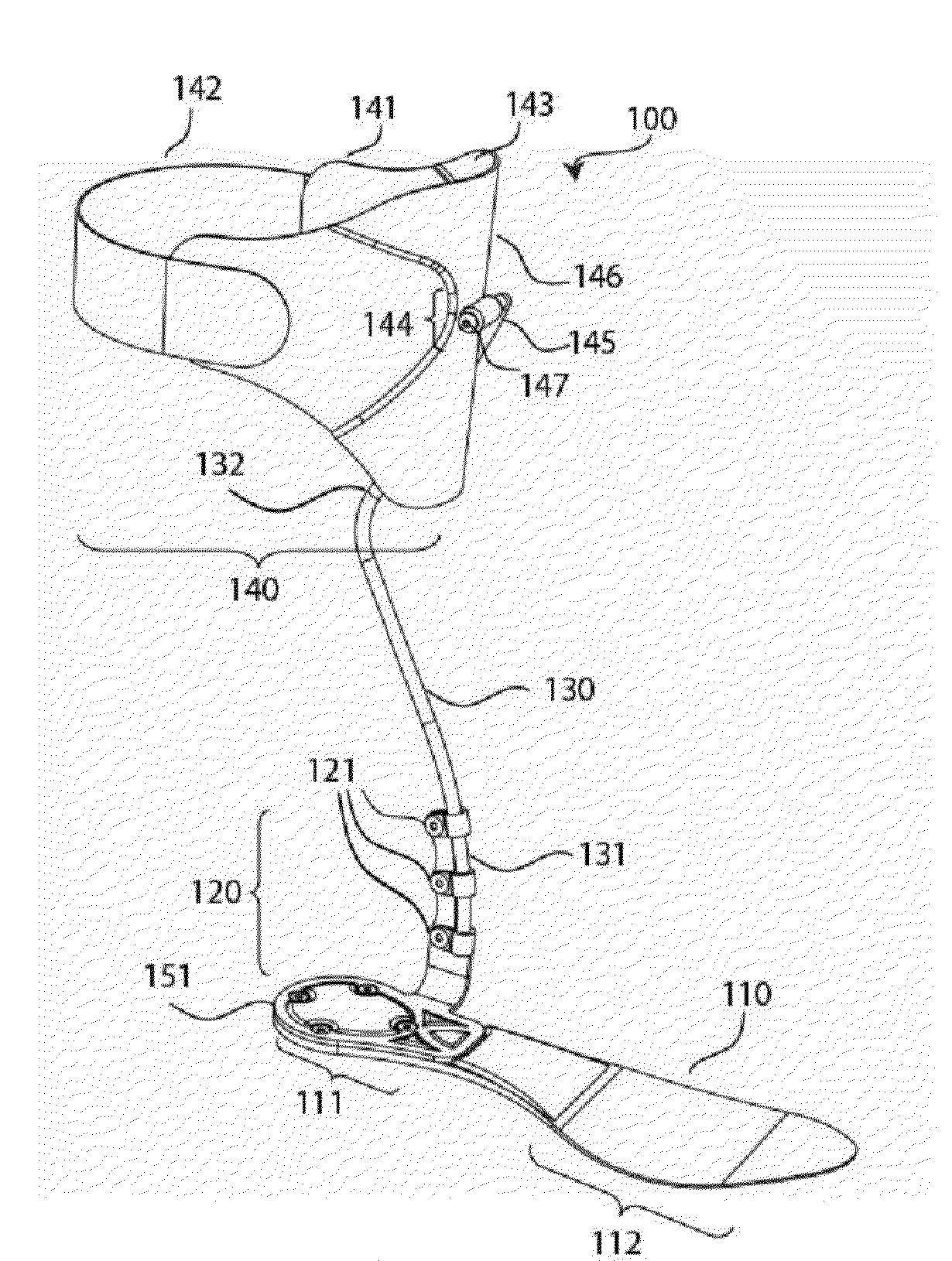
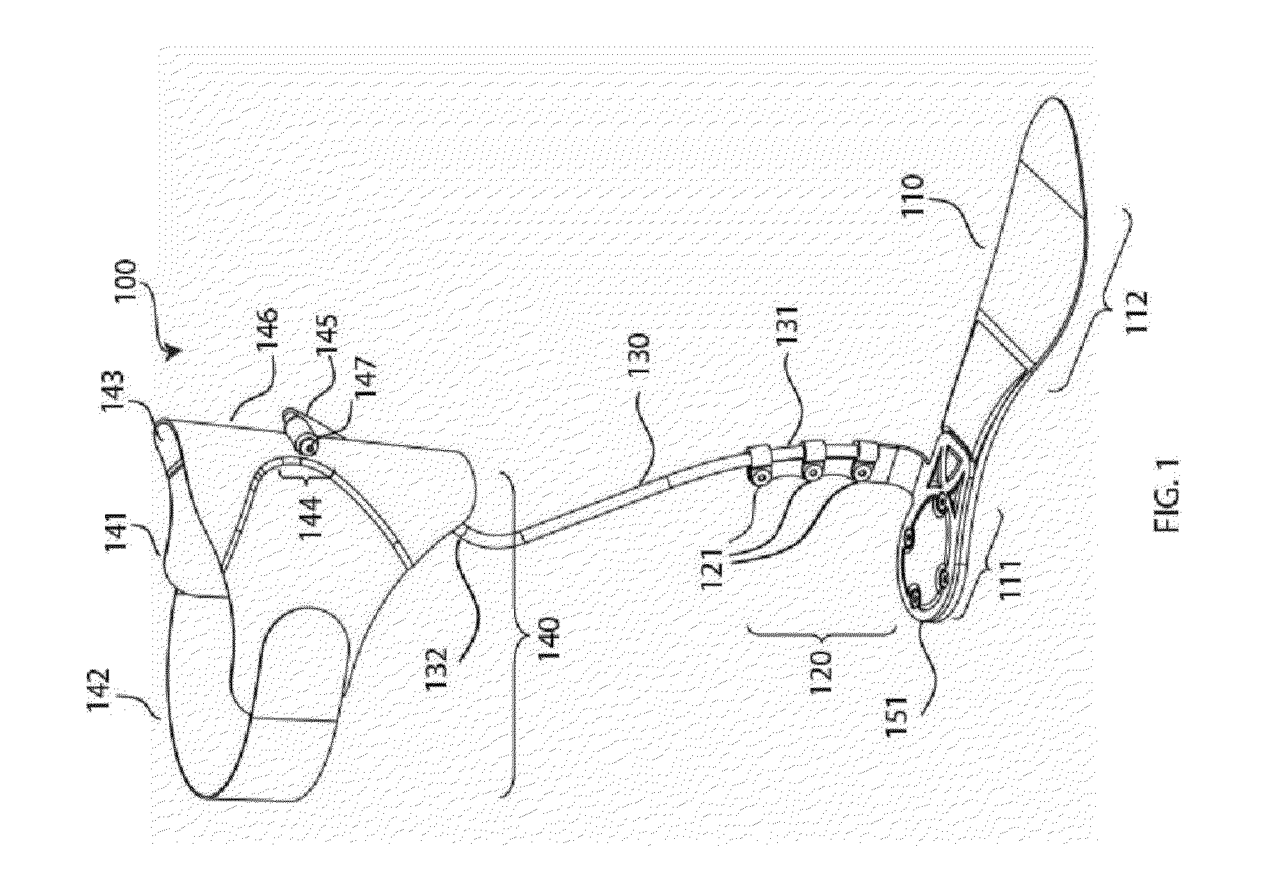
[0108]The present invention, in some embodiments thereof, relates to orthoses and, more particularly, but not exclusively, to an ankle foot orthosis.

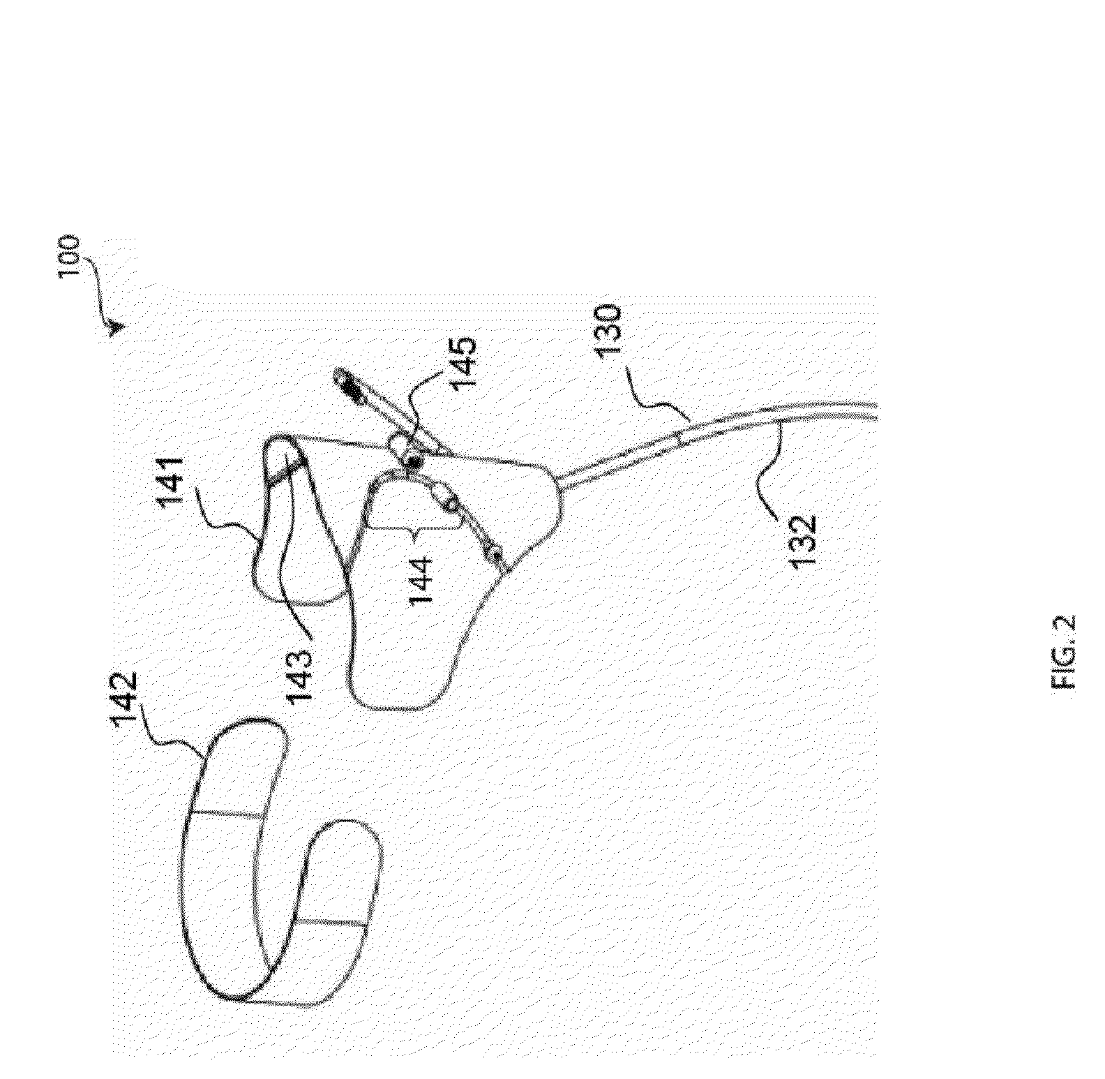
[0109]According to some embodiments of the invention, the AFO includes a flexible foot support to which a flexible elongate member is substantially fixedly coupled. The AFO further includes a lower-leg-holder that is mechanically coupled to an upper part of the elongate member. The AFO is designed in a manner such that when it is suitably engaged with a user drop foot, the AFO stores potential energy during, for example, the transition from the mid-stance to the terminal-stance phase of the user gait cycle. At least some of the stored potential energy is optionally released during the subsequent toe-off phase of the user gait cycle, whereby the released potential energy may at least partially compensate for, e.g., the muscle weakness in the drop foot. Consequently, the AFO optionally causes ground clearance of the user drop foot during ...


PUM


Abstract

Disclosed is an ankle foot orthotic device for assisting a user during gait. The device comprises: a foot support having a shape and size configured to the plantar aspect of a user foot, the foot support having a forward portion and a rearward portion and a heel plate coupled to an upper surface of the rearward portion. The device further comprises: an upper rod having a longitudinal axis and a lower end connected to an offset and a lower rod having: a longitudinal axis; a lower end connected to the heel plate; and an upward end connected to the offset.

Description

RELATED APPLICATION[0001]This application is a Continuation in Part of U.S. application Ser. No. 11 / 757,697, “An Ankle Foot Orthosis Device”, filed 4 Jun. 2007; the content of which is incorporated by reference as if fully set forth herein.FIELD AND BACKGROUND OF THE INVENTION[0002]The present invention, in some embodiments thereof, relates to orthoses and, more particularly, but not exclusively, to an ankle foot orthosis.[0003]Drop foot, also known as steppage gait, is a condition in which there is a deficit in pivoting the foot upward toward the anterior of the tibia, herein dorsiflexion, due to neurologic and / or muscular malfunction.[0004]To prevent tripping during swinging forward, herein swing phase of gait, the affected leg must be lifted high off the ground and dropped into place in front of the other foot, referred to as a steppage gait.[0005]In “swing phase” of gait, the drop foot remains in the “dropped”, herein plantiflexed position and often barely clears the ground duri...

Claims


Application Information

Patent Timeline
IPC IPC(8): A61F5/00
CPCA61F5/0111
Inventor SHLOMOVITZ, TAL
Owner YAAD ADVANCED ORTHOPEDICS
Learn More