Knee orthosis with hinged shin and thigh cuff

a knee and hinge technology, applied in the field of knee orthosis, can solve the problems of reducing body energy, reducing the effect of muscle atrophicity, and reducing the stability of the knee, so as to reduce or eliminate unwanted pressure, prevent the slippage of the brace, and add stability to the knee

Active Publication Date: 2012-11-13
NACE RICHARD NACE
View PDF14 Cites 39 Cited by
  • Summary
  • Abstract
  • Description
  • Claims
  • Application Information

AI Technical Summary

Benefits of technology

[0009]The knee orthosis of the present invention provides all of the advantages needed, which are mentioned above and which are currently deficient and wholly missing from the prior art. The present knee orthosis is used and indicated for increased medial, lateral, and rotational support and control of the knee joint following injury to or reconstruction of the anterior cruciate ligament (ACL) and posterior cruciate ligament (PCL) or protection of the collateral ligament of the knee. The present invention provides increased support for patients who have continued symptoms of significant knee instability such as giving way, which may be due to poor quadriceps or hamstring strength (i.e., hemiplegia), or for patients who have a desire for early resumption of activities after knee surgery. The present knee orthosis is also useful after total knee replacement or high tibia osteotomy.
[0012]The lower shin cuff has a pair of hinges located proximal to the shin cuff opposed ends and left and right vertical strut lower end portions for permitting the shin cuff to pivot downwardly away from a shin of a person wearing the knee orthosis when a person flexes the knee or performs a squatting motion thereby reducing or eliminating unwanted pressure that is usually applied to the shin of a patient of a person when they flex the knee, walk or squat. The shin cuff can pivot upwards of 60-75 degrees.
[0013]The novel knee orthosis of the present invention also employs a plurality of air bladders used as therapeutic and corrective force elements for the device. The air bladders are removeably positionable along inner surfaces of the two vertical struts and hinges. Anywhere from one to six air bladders can be employed such that force can be applied on both sides of the knee joint, at the knee joint, directly above the knee joint on the inner and outer thigh area and directly below the knee joint on the inner and outer shin area. When employed they also provide additional stabilization to the knee, prevent brace slippage and provide an extra degree of comfort to patient.
[0014]The novel knee orthosis also employs elastic thigh and cuff cushion members positioned along the inner surfaces of the thigh and shin cuff, respectively, for providing more comfort and support. The elasticity of these cushions allows them to bend and flex with the movements of the patient but return to their stable positions after movement by the patient such that the patient's knee joint is continuously stabilized regardless of the movement made by the patient using the knee orthosis of the present invention.
[0015]In a first alternate embodiment, the upper thigh cuff also has a pair of hinges located proximal to the thigh cuff opposed ends and left and right vertical strut upper end portions for permitting the thigh cuff to pivot upwardly away from a thigh of a person wearing the knee orthosis when a person flexes the knee or performs any other motion thereby reducing or eliminating unwanted pressure that is usually applied to the thigh of a patient of a person when they flex the knee, walk or squat. The thigh cuff can pivot upwards of 60-75 degrees or more.

Problems solved by technology

Repetitive use of a joint, such as the knee, over time tends to reduce the stability of the knee.
Or to do so, results in great pain, which is usually treated with pain medications that can be addictive and hard on the liver and other important organs of the body.
Further, when there is a lack of movement of a patient due to knee instability, a sedentary lifestyle is usually taken up, which can result in a reduction of body energy, weight gain, atrophied muscles, especially around the knee joint, and a general depression of mental state due to the lack of ability of the person to be self-sufficient and mobile.
In fact, most apply unwanted pressures upon the thigh and the shin of the patient when the patient walks, squats or flexes the knee joint.
This therefore discourages the patient from performing any squatting action, which in turns encourages the patient to remain sedentary and results in the degradation of the physical and mental state.
Further, prior art knee orthotics do not employ therapeutic and corrective forces to the knee joint area and the surrounding leg musculature area.

Method used


Image

  • Knee orthosis with hinged shin and thigh cuff
  • Knee orthosis with hinged shin and thigh cuff
  • Knee orthosis with hinged shin and thigh cuff

Examples


Embodiment Construction

[0025]Throughout the following detailed description the same reference numerals refer to the same elements in all figures.

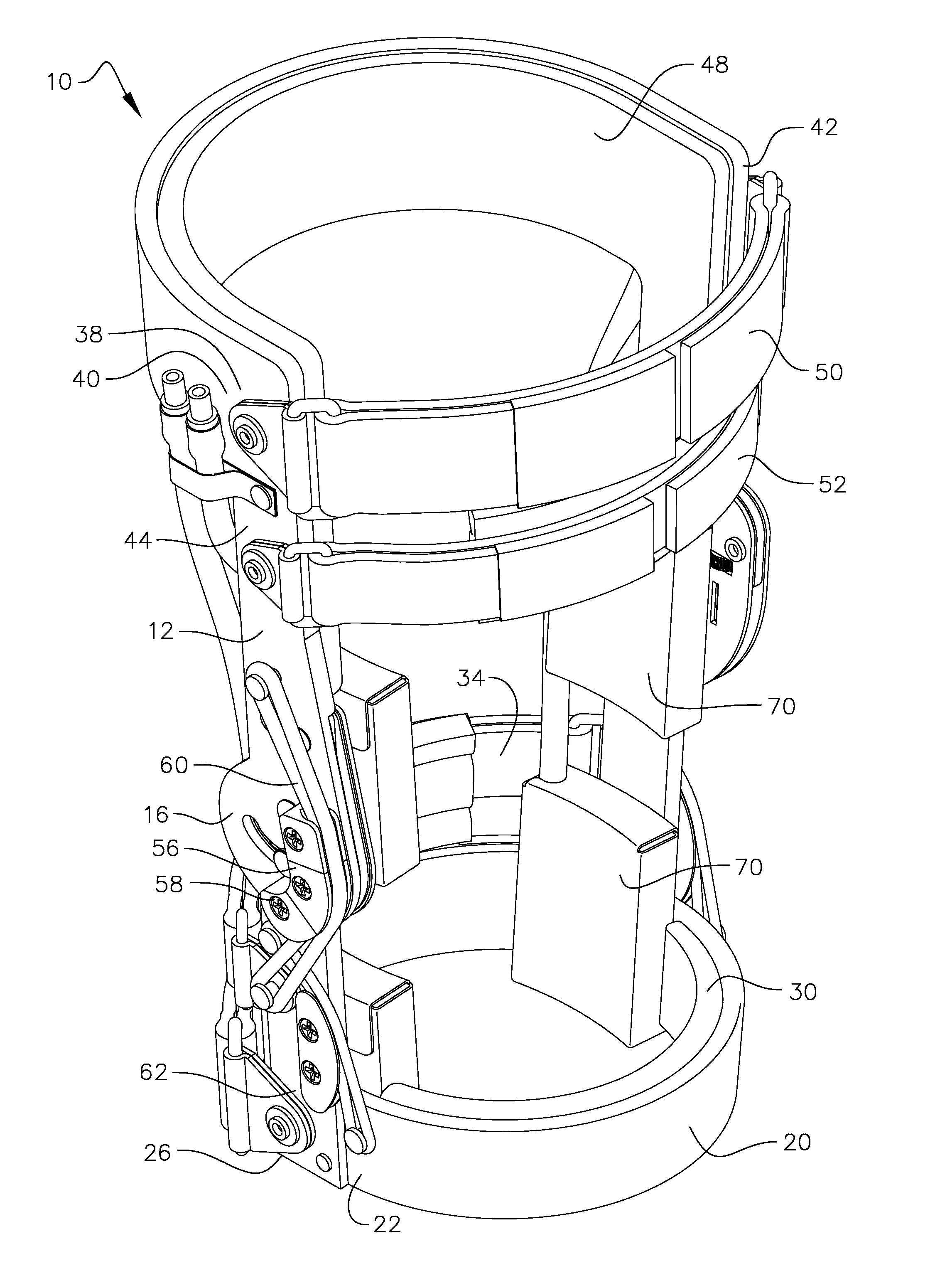
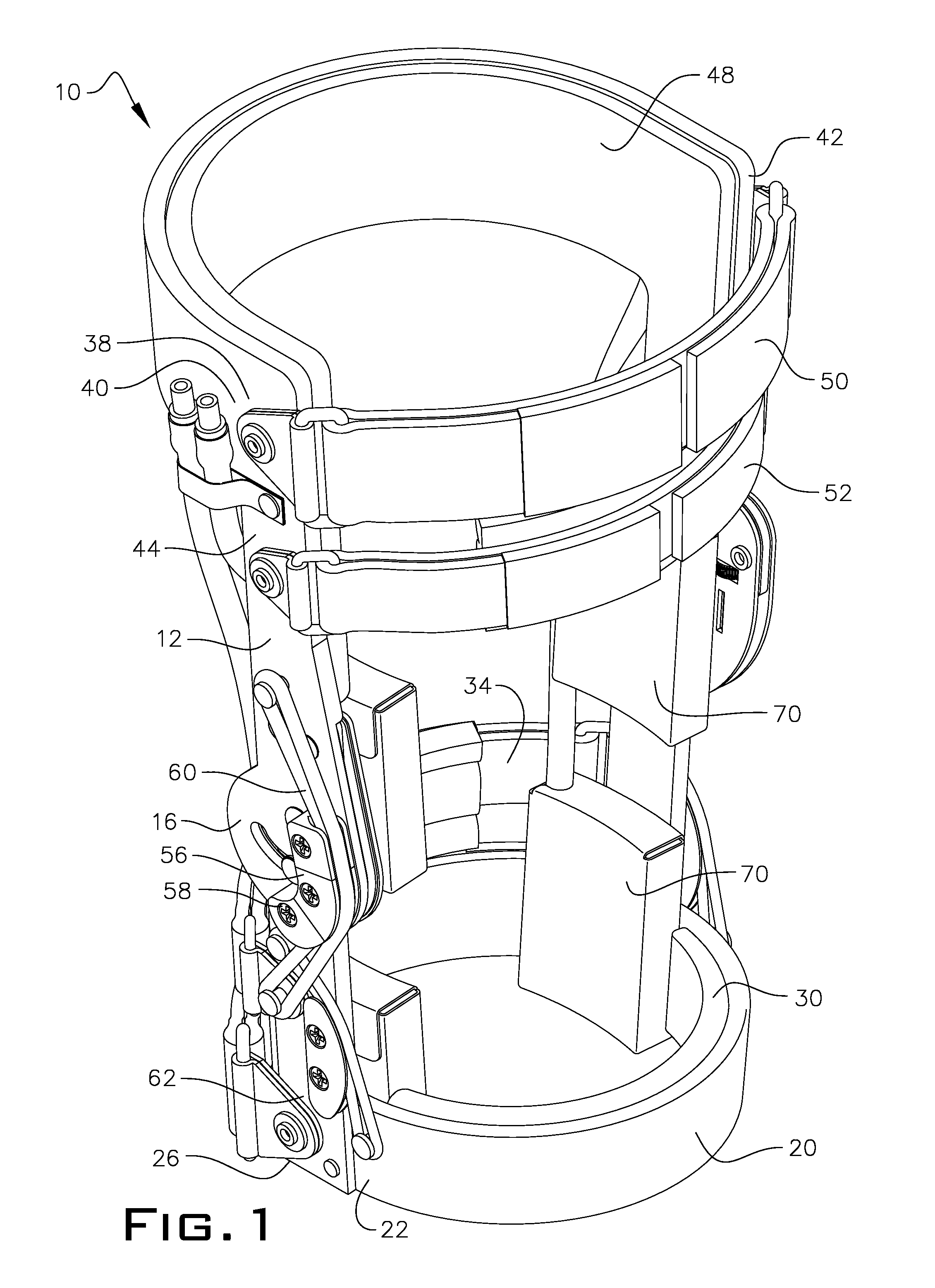
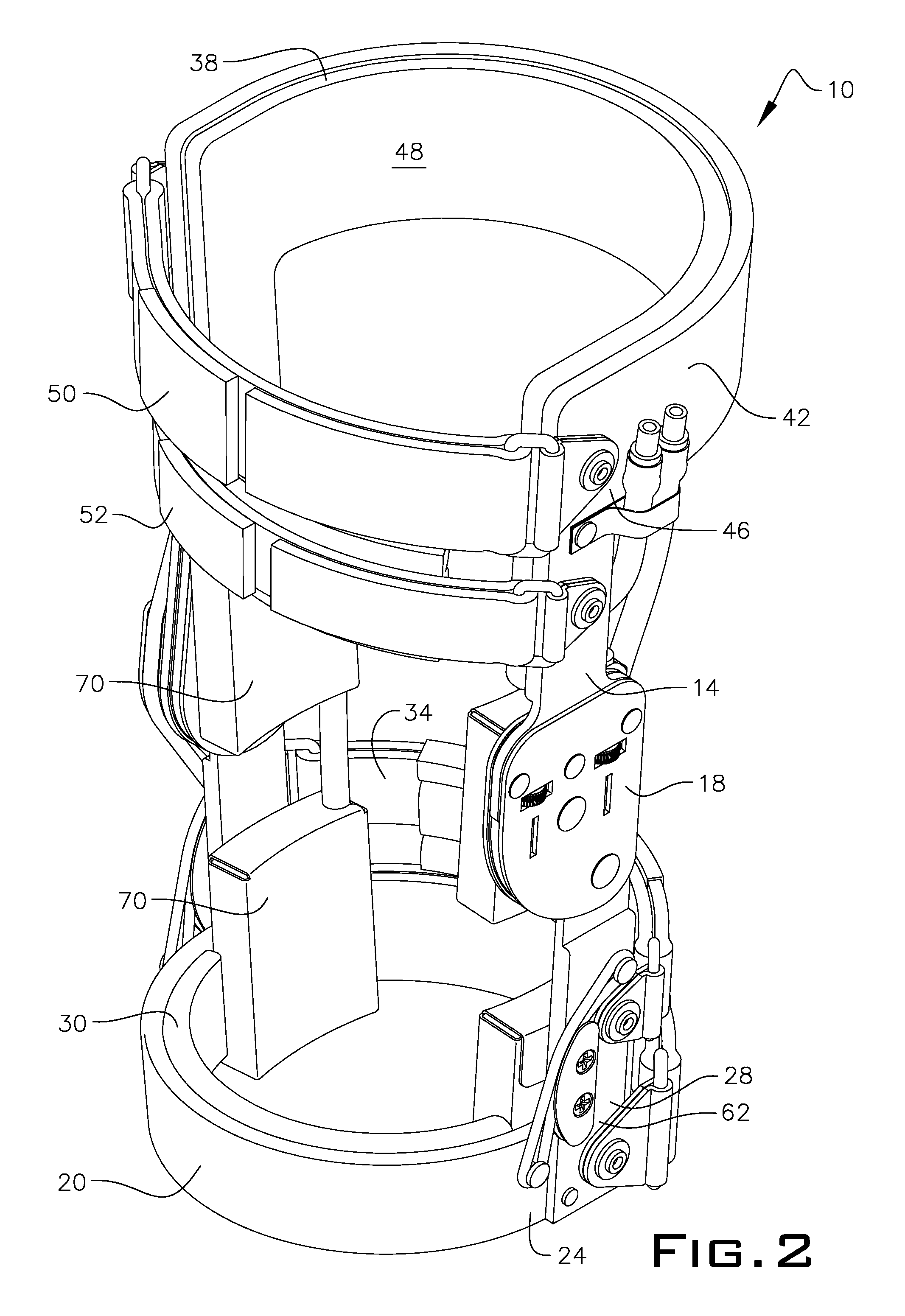
[0026]Referring to FIGS. 1 and 2, a knee orthosis 10 of the present is shown. As shown, knee orthosis 10 has a left side and right side vertical strut, 12 and 14, respectively. Struts 12 and 14 are generally parallel and when knee orthosis 10 is employed on a patient run along medial and lateral sides of a knee joint and thigh and shin area of the patient. Each strut has its own hinge 16 and 18 positioned intermediate top and bottom portions of struts 12 and 14 such that knee orthosis 10 pivots about said hinges when the knee joint of the patient is flexed. In the embodiment shown in FIGS. 1 and 2, hinge 16 is a polycentric hinge and hinge 18 is a uni-centric hinge. However, nothing herein limits the use of knee orthosis to this embodiment shown and described herein in this preferred embodiment. In fact, any combination of hinges could be employed.

[0027]Referring...


PUM


Abstract

A knee orthosis has two vertical struts positioned on opposed sides of a knee joint in a generally parallel relationship. Each vertical strut has a hinge member located at a general middle portion; each vertical strut has a top and bottom end portion. An upper thigh cuff attaches at opposed ends to the upper end portions of the two vertical struts whereas a lower shin cuff attaches at opposed ends to the lower end portions. The lower shin cuff has a pair of hinges located proximal to the shin cuff opposed ends for permitting the shin cuff to pivot downwardly away from a shin of a person wearing the knee orthosis. An alternate embodiment employs hinges located proximal to the thigh cuff opposed ends for permitting the thigh cuff to pivot upwardly away from a thigh of a person when the same motion is performed.

Description

PRIOR APPLICATIONS[0001]This is a non-provisional patent application that claims priority to provisional patent application 61 / 054,516, filed May 20, 2008.FIELD OF THE INVENTION[0002]The invention relates to a knee orthosis. More particularly, it refers to pre-operative, post operative knee orthosis for stabilizing a knee joint of a person before or after surgery or after injury thereto, that applies an adjustable corrective and therapeutic force to the knee joint and surrounding muscles above and below the knee and which also removes pressure from a lower shin cuff of the knee orthosis when a patient using the novel knee orthosis of this present invention flexes the knee joint or performs a body squatting motion through rotation about a shin cuff hinge.BACKGROUND OF THE INVENTION[0003]Orthosis devices and appliances commonly referred to as “orthotics,” are known in the prior art and have been utilized for many years by orthotists (a maker and fitter of orthotics), physical therapis...

Claims


Application Information

Patent Timeline
Patent Type & Authority Patents(United States)
IPC IPC(8): A61F5/00
CPCA61F5/0125A61F2005/0172A61F2005/0179
Inventor NACE, RICHARD A.
Owner NACE RICHARD NACE
Why Eureka
Try Eureka