System and method for starting a wound rotor motor

a rotor motor and wound technology, applied in the direction of motor/generator/converter stopper, dynamo-electric converter control, conversion with intermediate conversion to dc, etc., can solve the problem of high rotor circuit power

Active Publication Date: 2009-03-31
TMEIC
View PDF27 Cites 4 Cited by
  • Summary
  • Abstract
  • Description
  • Claims
  • Application Information

AI Technical Summary

Problems solved by technology

From these equations, it becomes clear that slow motor speed and high torque, which can be the case at starting, can lead to high rotor circuit power.
However, this protection is achieved by means of inclusion in the starting circuit of expensive and bulky resistance and breaker devices.

Method used


Image

  • System and method for starting a wound rotor motor
  • System and method for starting a wound rotor motor
  • System and method for starting a wound rotor motor

Examples


Embodiment Construction

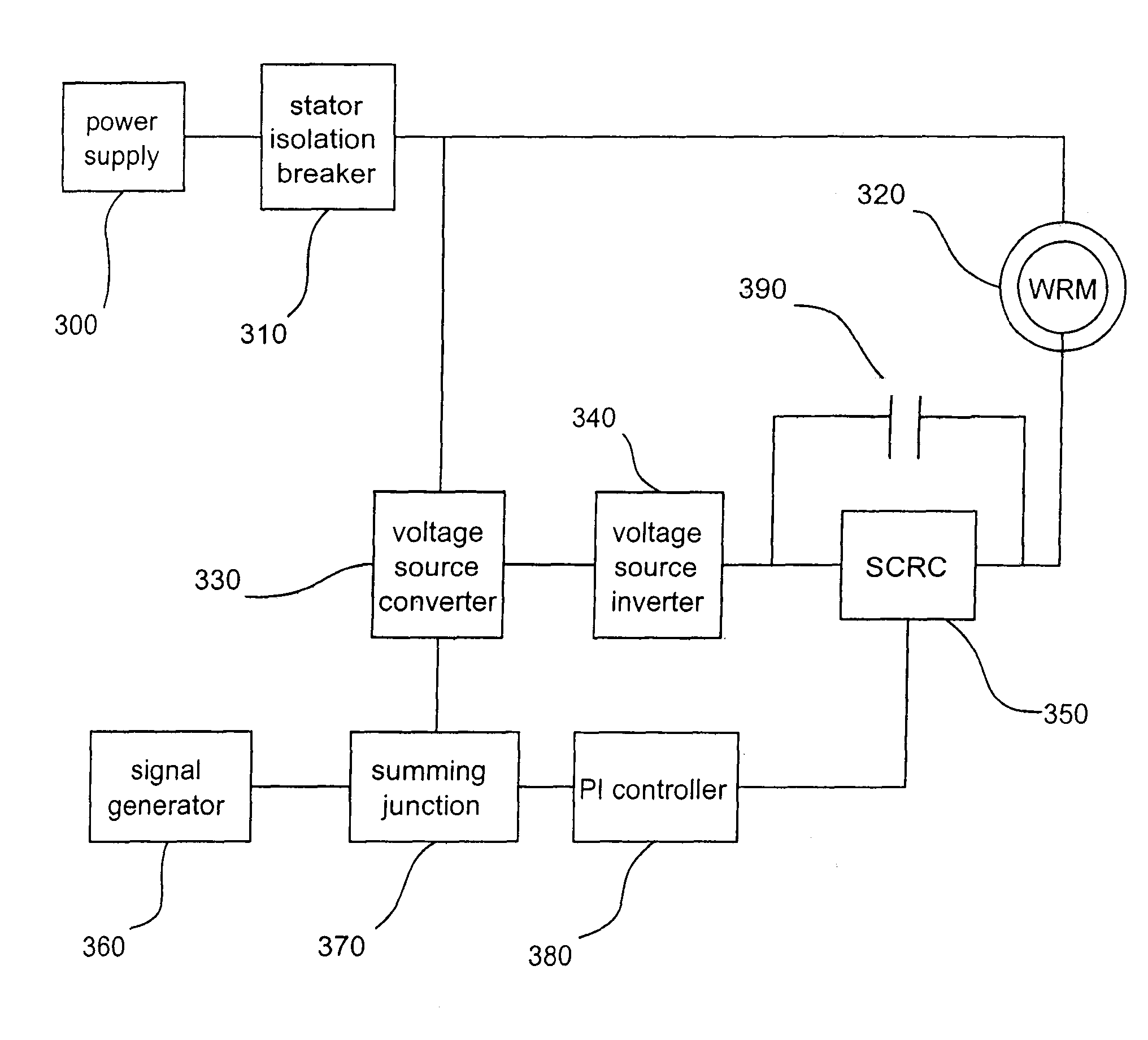
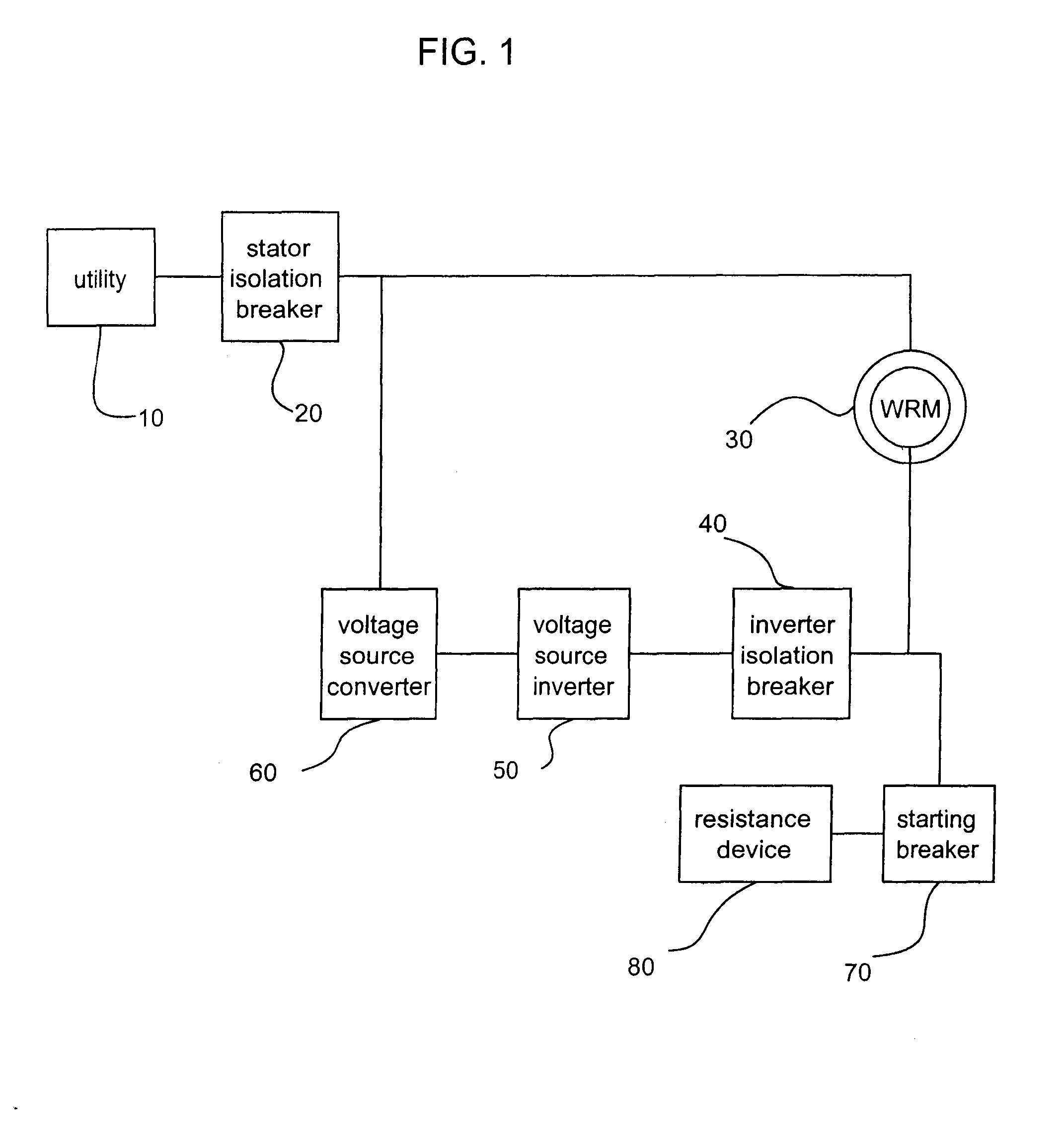
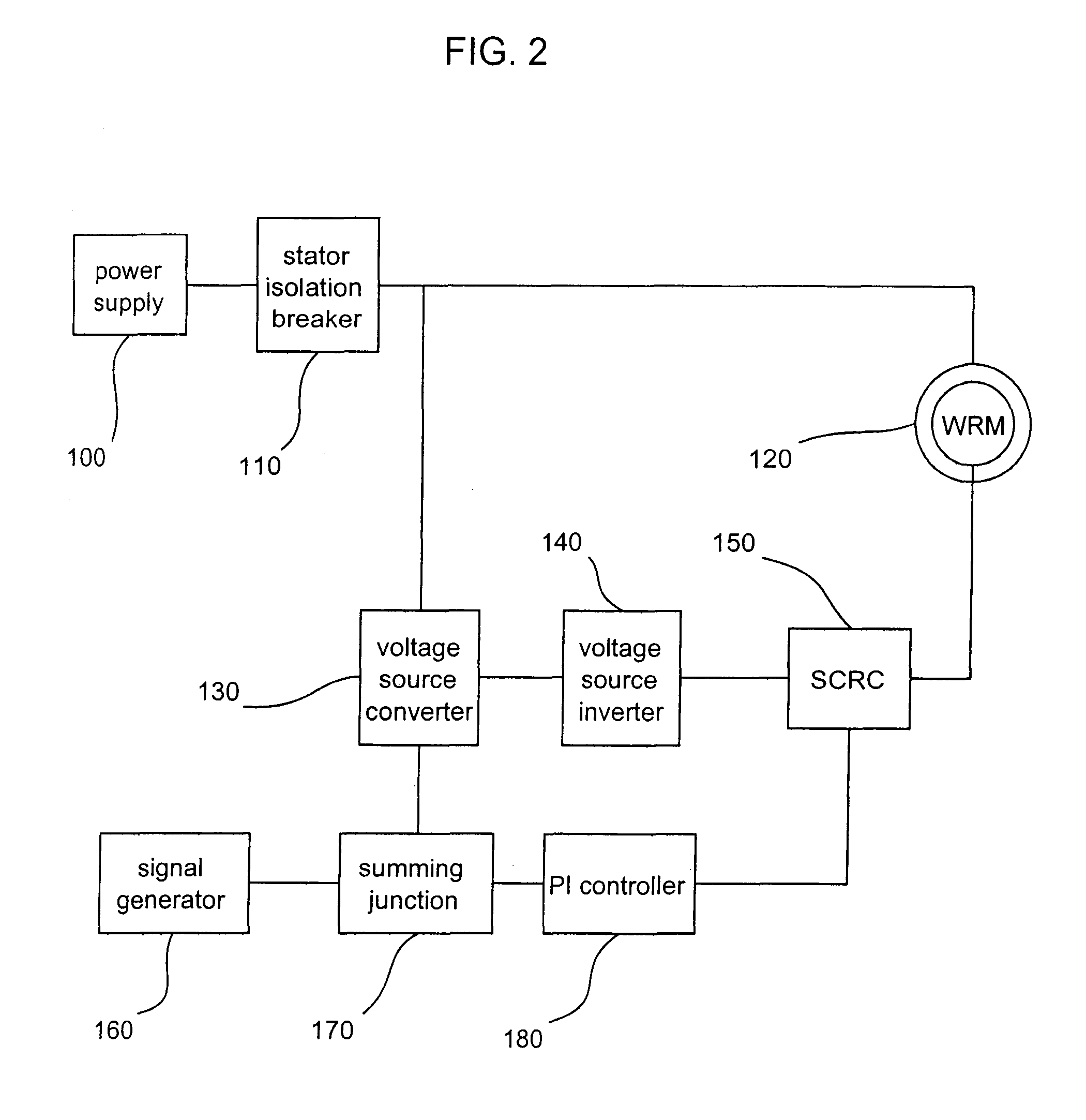
[0016]For a more detailed understanding of the invention, reference is first made to FIG. 2 of the drawings which presents a block diagram view of the components in the preferred embodiment of the starting circuit of this invention. As in FIG. 1, power is provided from a power supply 100, such as a utility mains, generator or any other source of AC power, through a protective stator isolation breaker 110 to a wound rotor motor 120. Typically, three phase power is provided in such a system although other arrangements are possible depending on specific system requirements. Stator isolation breaker 110 provides thermal protection of the motor circuit, allows for disconnection of the motor and drive elements for maintenance and provides protection against short circuit faults anywhere in the system.

[0017]The drive elements include VSC 130 and VSI 140. VSC 130 is an isolated gate bipolar transistor (IGBT)-based DC / AC power supply and is connected through an AC bus to stator isolation bre...


PUM


Abstract

A system and method for starting and regulating a wound rotor motor (320) including a phase-controlled SCR converter (350) and a drive circuit (330, 340) having a voltage source inverter (340) and a voltage source converter (330). The SCR converter (350) regulates power transmitted to the drive circuit from the rotor of the motor so that the ratings of the drive circuit are not exceeded. A shorting contactor (390) is employed in various embodiments to increase the efficiency of the circuit.

Description

CROSS-REFERENCES TO RELATED APPLICATIONS[0001]This application is a continuation-in-part of PCT / US2005 / 016862, filed on May 13, 2005, which is incorporated herein by reference in its entirety.TECHNICAL FIELD[0002]The subject invention relates generally to a system and method for starting a wound rotor motor used in industrial applications. More particularly, the system and method provide an economical and efficient starting circuit for such a motor by arranging conventionally known components in a novel configuration.BACKGROUND OF THE INVENTION[0003]A wound rotor motor (WRM) can be controlled using a voltage source inverter (VSI) in combination with a voltage source converter (VSC) so that variable motor speed and torque are obtained. An advantage of a this type of system is that only a fraction of the power delivered by the motor to the shaft which it drives must be handled by the drive system, i.e. the VSI / VSC combination. This is a desirable feature since the cost of the drive sy...

Claims


Application Information

Patent Timeline
Patent Type & Authority Patents(United States)
IPC IPC(8): H02P1/26H02M5/458
CPCH02P1/16H02P27/05H02P27/16
Inventor BIXEL, PAUL S.
Owner TMEIC
Why Eureka
Try Eureka