Mower with ground following cutting deck and weight transfer between deck and frame

a mower and cutting board technology, applied in the field of outdoor power equipment and to mowers, can solve the problems of not changing the basic drive system of the mower, the mower may not be used, and the tractive ability of the mower, particularly of the large riding mower carrying a seated operator, is not ideal or well suited for such a slick surfa

a mower and cutting board technology, applied in the field of outdoor power equipment and to mowers, can solve the problems of not changing the basic drive system of the mower, the mower may not be used, and the tractive ability of the mower, particularly of the large riding mower carrying a seated operator, is not ideal or well suited for such a slick surfa

US7520114B2Active Publication Date: 2009-04-21TORO CO THE

Image

  • Mower with ground following cutting deck and weight transfer between deck and frame
  • Mower with ground following cutting deck and weight transfer between deck and frame
  • Mower with ground following cutting deck and weight transfer between deck and frame

Examples


Embodiment Construction

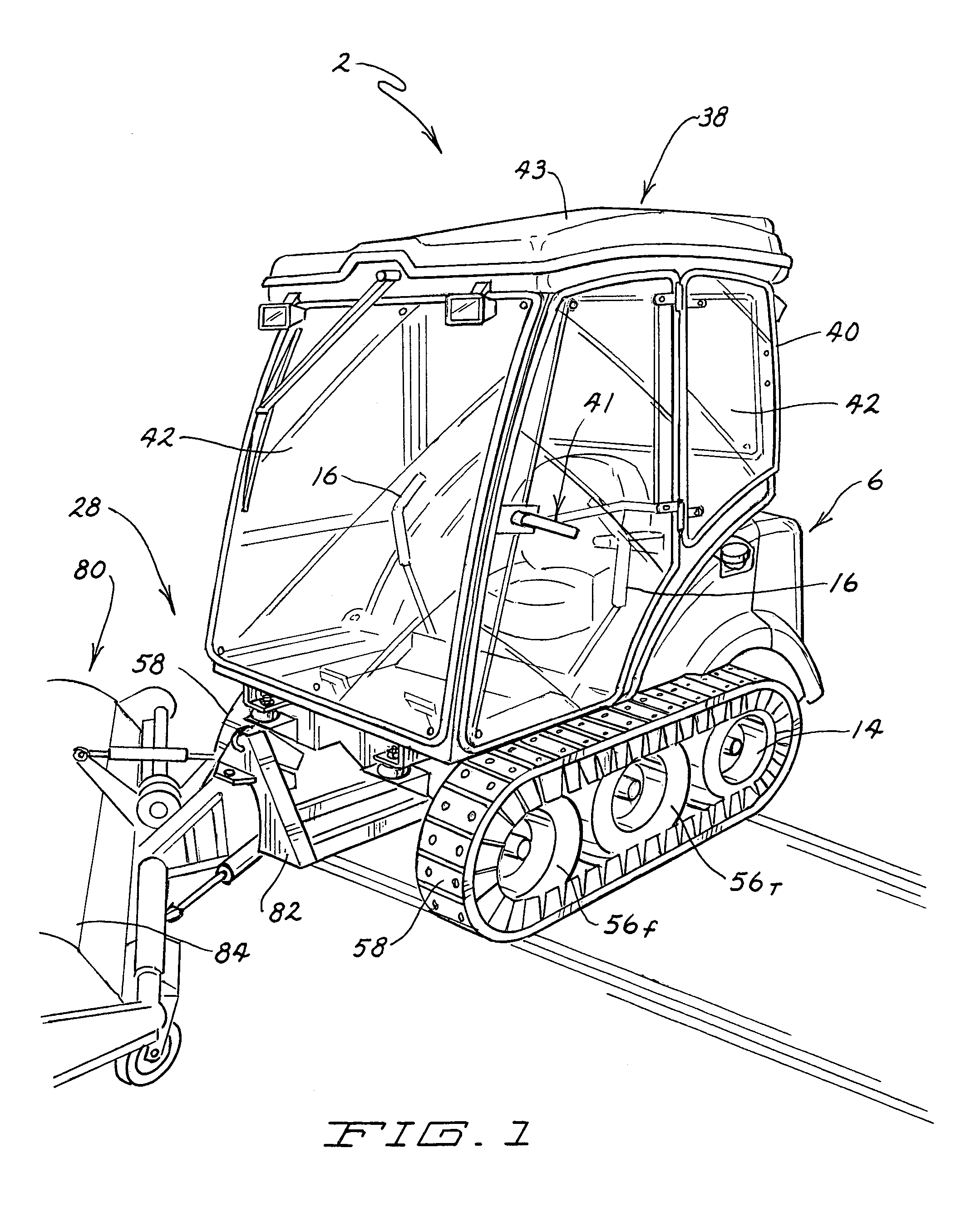
[0030]FIG. 1 illustrates one embodiment of a tracked implement 2 according to this invention. Implement 2 preferably can be converted from a zero radius turn (ZRT) mower 4 as shown in FIG. 5 and vice versa. In other words, as will be explained in more detail hereafter, mower 4 can be changed into implement 2 and implement 2 can be changed back into mower 4. This conversion is one aspect of this invention.

[0031]However, implement 2 and mower 4 need not necessarily be convertible into the other. Both implement 2 and mower 4 could be provided as complete machines that would not undergo any conversion. Other aspects of this invention relate to how the endless tracks on implement 2 are supported. Yet other aspects of this invention relate to how a cutting deck is suspended from mower 4. These other aspects of this invention are not dependent upon being used only in a convertible implement 2 and mower 4.

The Drive Unit

[0032]There is a portion of both mower 4 and implement 2 that is common ...


PUM


Abstract

This invention relates to a mower and a tracked implement that convert from one to the other by coupling a mower unit or a tracked unit to a common drive unit. The drive unit is thus used in both products to provide cost savings in the purchase of the equipment. In the tracked unit, a cab for enclosing the operator's station is part of the tracked unit and gets mounted to the drive unit when the tracked unit is coupled to the drive unit. A pair of idlers rotate on pivot axes that are fixed relative to a pivotal idler support that carries the idlers. The pivot point for the idler support is chosen to prevent track elongation when the tracked unit climbs obstructions such as a curb. In the mower unit, a relatively heavy cutting deck is used and spring biased weight transfer arms transfer some of the deck weight to the mower frame.

Description

TECHNICAL FIELD[0001]This invention relates generally to the field of outdoor power equipment and to a mower that is convertible to a tracked implement and vise versa. More particularly, this invention relates to how the mower and tracked implement convert using a common drive unit and to various features of the mower and tracked implement.BACKGROUND OF THE INVENTION[0002]In the field of outdoor power equipment, riding mowers are known for cutting large areas of grass. Such mowers typically comprise a frame carrying a prime mover and a cutting deck mounted to the frame. The frame is supported for rolling over the ground by a pair of front caster wheels and a pair of rear drive wheels that are driven in some fashion from the prime mover. The drive wheels are often independently drivable in forward and reverse to provide zero radius turn (ZRT) capability. An operator is carried on a seat provided on the frame and operates the drive wheels and steers the frame using various controls ad...

Claims


Application Information

Patent Timeline
21 Apr 2009
Publication
US7520114B2
IPC
A01D34/00
CPC
A01D42/08
Inventors
BERGSTEN, REX R.; ANDERSON, BRANDON J.