Riser buoyancy adjustable thrust column

a technology of adjustable thrust column and riser, which is applied in the direction of special purpose vessels, sealing/packing, and borehole/well accessories. it can solve the problems of complex devices or use friction to resist upward movemen

Active Publication Date: 2012-12-04
HYDRIL USA DISTRIBUTION LLC
View PDF25 Cites 15 Cited by
  • Summary
  • Abstract
  • Description
  • Claims
  • Application Information

AI Technical Summary

Problems solved by technology

The devices may be complex or use friction to resist the upward movement.

Method used


Image

  • Riser buoyancy adjustable thrust column
  • Riser buoyancy adjustable thrust column
  • Riser buoyancy adjustable thrust column

Examples


Embodiment Construction

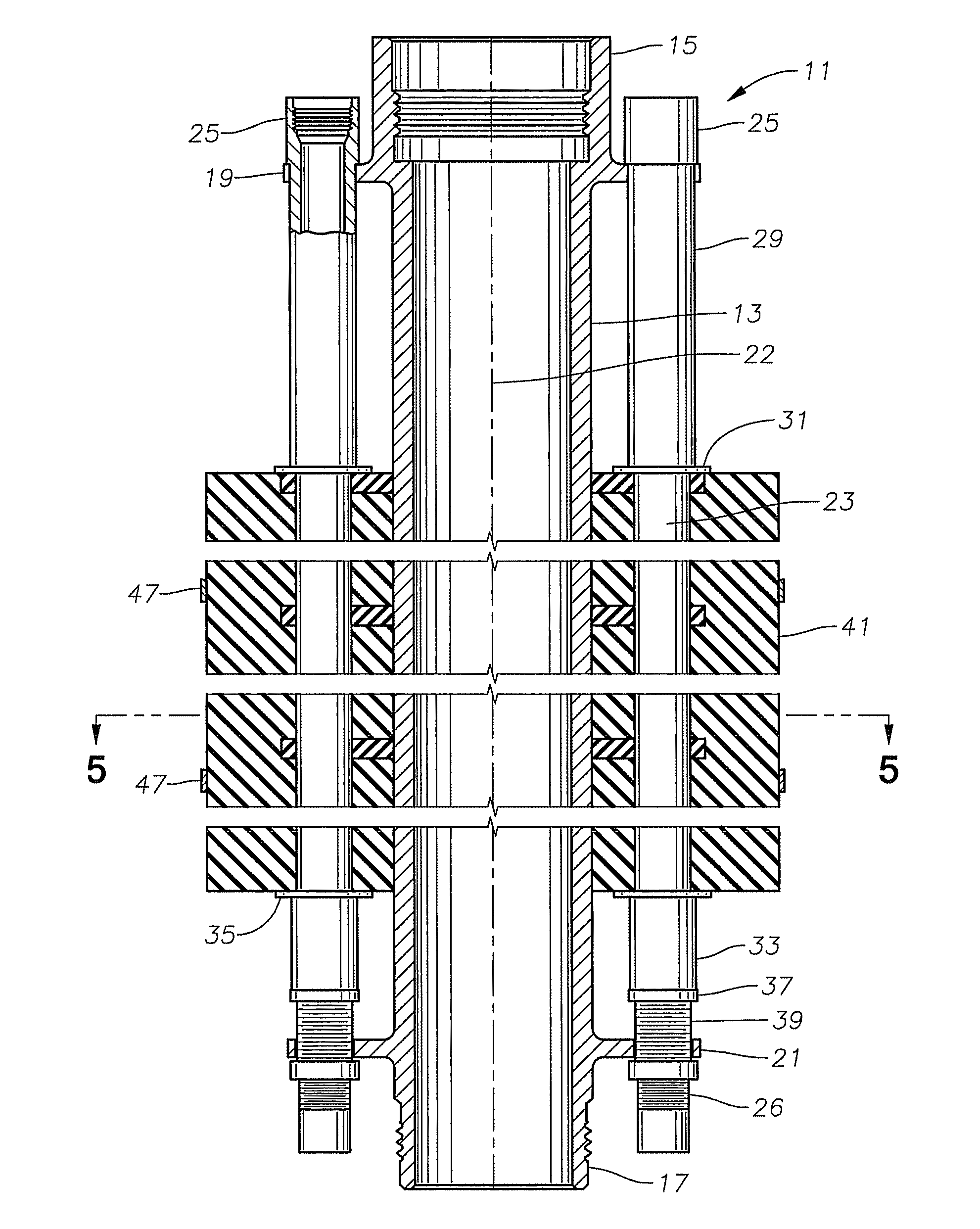
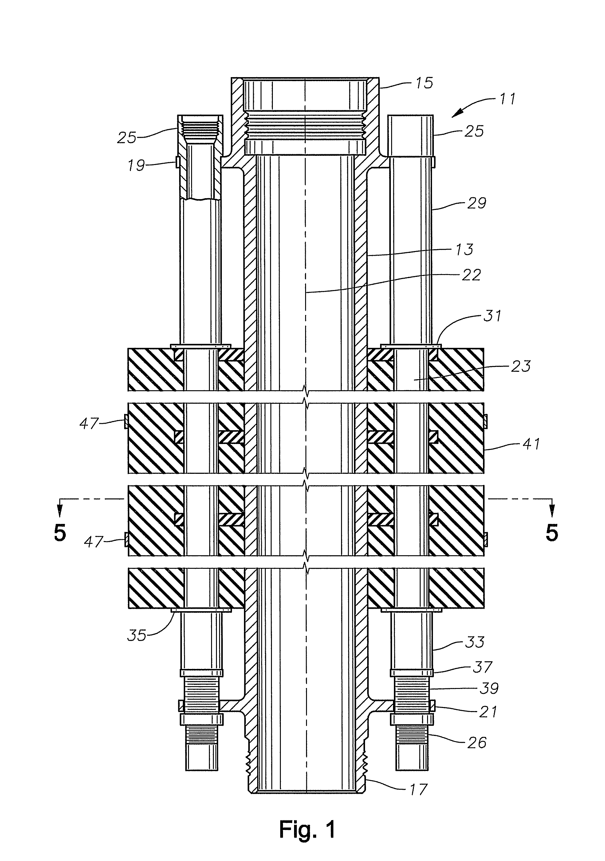
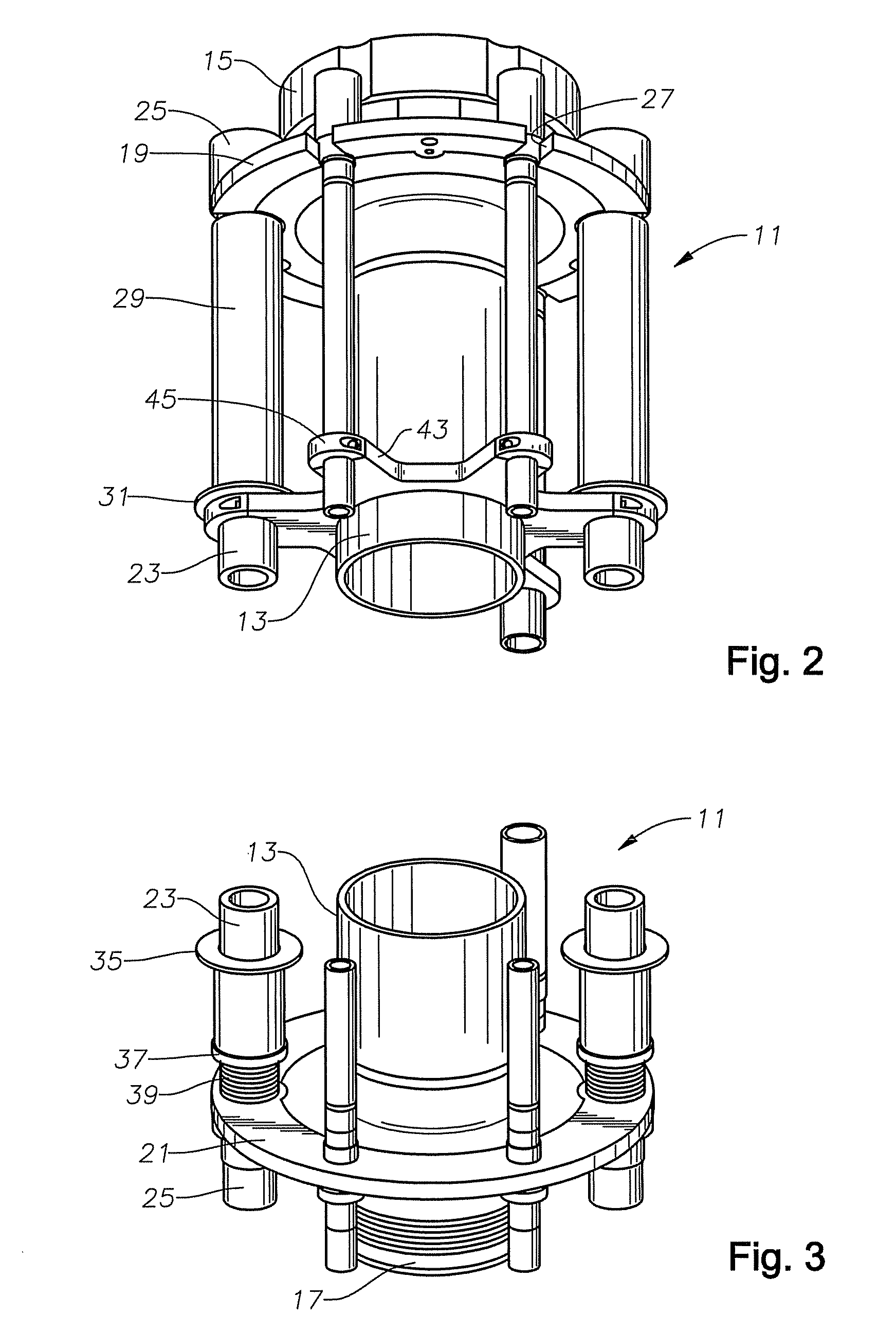
[0014]Referring to FIG. 1, one section of a riser joint assembly 11 is illustrated. Riser joint assembly 11 is typically from about 5-90 feet in length and is coupled into a string of riser extending from a drilling vessel to a subsea wellhead. Riser joint assembly 11 has a main riser pipe 13, which has an upper connector 15 on one end and a lower connector 17 on the other end. In this embodiment, upper connector 15 is a box-type connection and lower connector 17 is a pin-type connector for connecting to a box of a mating riser assembly. Connectors 15, 17 may be conventional members and could be reversed, if desired.

[0015]An upper support flange 19 extends radially outward from upper connector 15. Similarly, a lower support flange 21 extends radially outward from lower connector 17. Support flanges 19 and 21 are located in parallel planes perpendicular to an axis 22 of main riser pipe 13.

[0016]Several auxiliary pipes or lines 23 are mounted around and parallel to main riser pipe 13....


PUM


Abstract

An offshore drilling riser joint has a central riser pipe, a number of auxiliary lines mounted around it, and a buoyancy module assembly of a buoyant material. A pair of upper thrust sleeves slide over two of the auxiliary lines, each of the upper thrust sleeves having a flange in contact with an upper end of the buoyancy module assembly. Each of the upper thrust sleeves transfer upward thrust imposed by the buoyancy module assembly to an upper support flange mounted to the central riser pipe. A pair of lower thrust sleeves slide over two of the auxiliary lines. Each lower thrust sleeve has a lower thrust flange that is engaged by a lower end of the buoyancy module assembly. Each of the lower thrust sleeves transfer weight of the buoyancy module assembly while out of water to a lower support flange mounted to the central riser pipe.

Description

CROSS REFERENCE TO RELATED APPLICATION[0001]This application claims priority to provisional application Ser. No. 61 / 173,401, filed Apr. 28, 2009.FIELD OF THE INVENTION[0002]This invention relates in general to drilling risers for offshore well drilling, and in particular to a device for handing forces imposed by buoyancy modules attached to the drilling risers.BACKGROUND OF THE INVENTION[0003]Drilling risers are employed while drilling an offshore well. The drilling riser extends from a subsea wellhead on the sea floor to a drilling platform on the surface. A typical drilling riser has a central riser pipe and a number of auxiliary pipes or lines. The operator rims drill pipe, casing, and various tools through central pipe of the riser. The auxiliary lines are parallel to the central pipe, spaced around it, and have smaller diameters. The operator supplies hydraulic fluid through some of the auxiliary lines and employs others as choke and kill lines.[0004]Normally, drilling risers u...

Claims


Application Information

Patent Timeline
Patent Type & Authority Patents(United States)
IPC IPC(8): E21B17/01
CPCE21B17/012
Inventor LARSON, ERIC D.STRINGFELLOW, RICK L.BULLARD, JESSE L.REAMS, JIM R.
Owner HYDRIL USA DISTRIBUTION LLC
Why Eureka
Try Eureka