
Wheeled distance measuring device

a technology of distance measurement and wheel, which is applied in the direction of measuring wheels, electric/magnetic measuring arrangements, instruments, etc., can solve the problems of inability to have a precise measurement, too long brake cables and initialization cables,

Active Publication Date: 2009-05-26
TECHTRONIC POWER TOOLS TECHNOLOGY LTD
View PDF7 Cites 28 Cited by
  • Summary
  • Abstract
  • Description
  • Claims
  • Application Information

AI Technical Summary

Benefits of technology

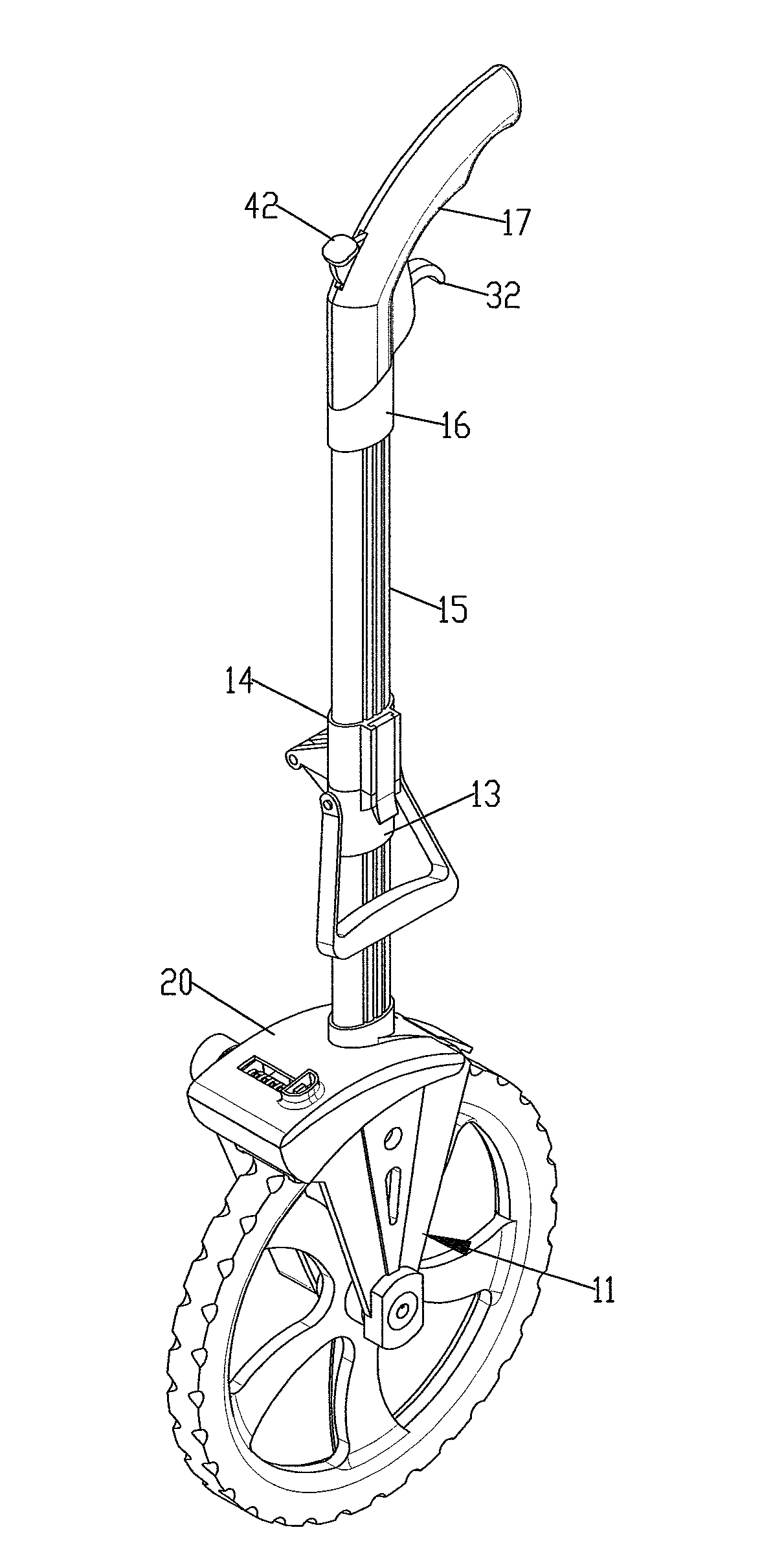
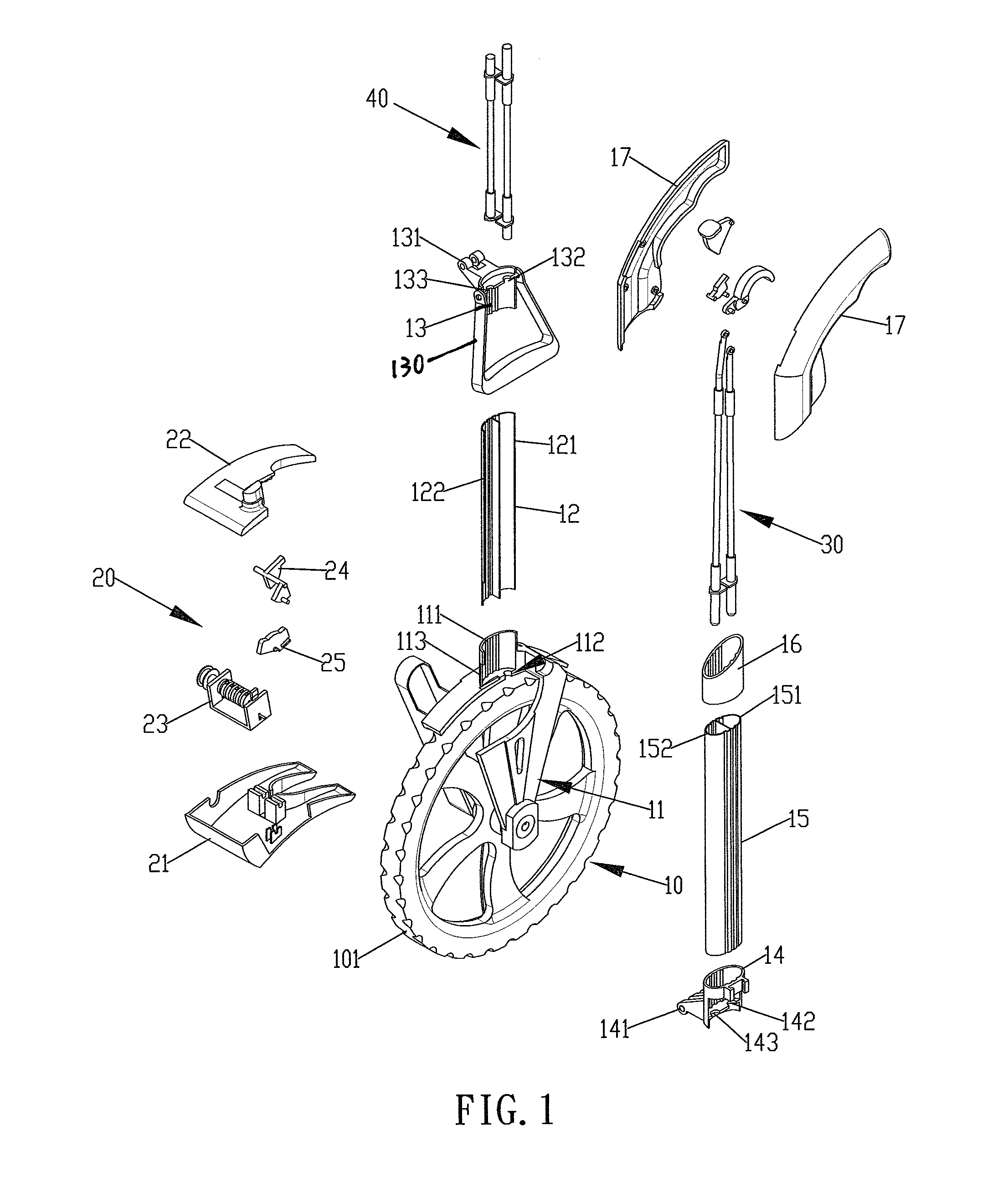
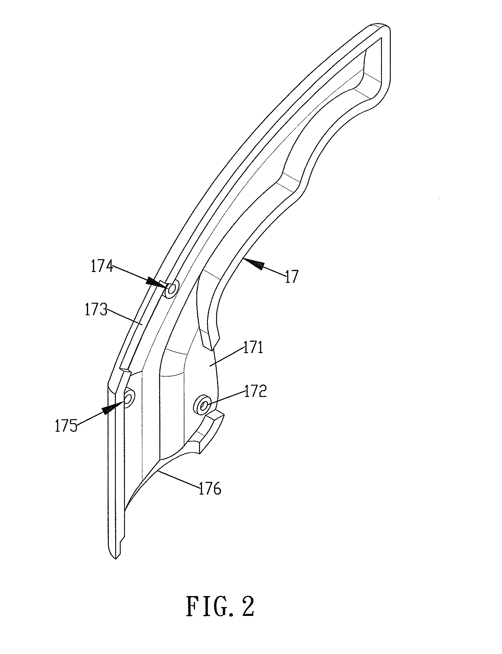
[0005]The present invention relates to a wheeled distance measuring device and the device comprises a wheel with a front fork connected thereto and a pole unit is connected to the front fork. The pole unit includes a first tube, a second tube, a third tube, a fourth tube and a fifth tube. A handle is connected to the fifth tube and includes a first control slot, a second control slot and a third control slot. A measuring unit is connected to a side of the front fork and includes a base, a top cover, a counter, a first arm and a second arm. The base is connected to the front fork and the top cover is mounted onto the base so as to receive a counter therein. The counter includes a rotary portion which is rotated when the wheel rolls. The first arm is located in the base and has a first control member which has an end received in the first tube. The second arm is located in the base and driven by the first arm. The second arm can initialize the counter.
[0006]A brake unit includes a first brake rod, a brake key and a second brake rod, wherein the first brake rod is received in the fourth tube and a first link is connected to a top of the first brake rod. A first contact section is connected to a lower end of the first brake rod and located in the third tube. The brake key extends through the first control slot of the handle and is pivotably engaged with the first recess of the handle. The first link is pivotably connected to a protrusion on the brake key. The second brake rod is received in the first tube and a top of the se

Problems solved by technology

However, the measuring unit, the pole unit and the handle are located on one side of the wheel so that the wheeled distance measuring device is not in a balance status so that when rolling the wheel to measure distance, the wheeled distance measuring device tends to move toward a side and this requires the user to correct it and cannot have a precise measurement.
Besides, the brake cable and the initialization cables are too long to be broken.

Method used


Image

  • Wheeled distance measuring device
  • Wheeled distance measuring device
  • Wheeled distance measuring device

Examples


second embodiment

[0041]FIGS. 16 to 19 show the brake unit 30 and the initialization unit 40, wherein the fourth engaging notch 322 of the brake key 32 is pivotably engaged with an elongate slot in the first link 311, and the seventh pivot 433 of the pivotal member 43 is pivotably engaged with an elongate slot in the second link 411.

third embodiment

[0042]FIGS. 20 to 23 show the brake unit 30 and the initialization unit 40, wherein the brake unit 30 includes a third contact section 34 which is pivotably connected between the fourth engaging notch 322 and the first link 311. The initialization unit 30 includes a fourth contact section 45 which is pivotably connected between the seventh engaging notch 433 and the second link 411.

[0043]The wheeled distance measuring device of the present invention includes an advantage which is a balance of weight on two sides of the wheel unit 10. The brake and initialization function can be directly controlled from the handle 17. The brake unit 30 and the initialization unit 40 are operated by rods which are reliable and durable.

[0044]While we have shown and described the embodiment in accordance with the present invention, it should be clear to those skilled in the art that further embodiments may be made without departing from the scope of the present invention.


PUM


Abstract

A wheeled distance measuring device includes a wheel unit having a wheel and a front fork with which the wheel is rotatably connected. A pole unit is connected to the front fork and a handle is connected to a top of the pole unit. A measuring unit is connected to a side of the front fork and a brake unit and an initialization unit are connected to the measuring unit. The brake unit and the initialization unit have a brake key and an initialization key received in the handle. Two respective rods are connected to the brake and initialization keys respectively and extend through the pole unit and connected to the measuring unit. By operating the brake key and the initialization key, the wheel can be braked and the measuring unit can be initialized respectively.

Description

FIELD OF THE INVENTION[0001]The present invention relates to a wheeled distance measuring device including a folding pole which has a handle connected thereto, a brake key and an initialization key are installed to the handle.BACKGROUND OF THE INVENTION[0002]A conventional distance measuring device is disclosed in U.S. Pat. No. 7,040,036 to Hui Chen Wang who is the wife of applicant and includes a wheel rotatably connected to a pole and a measuring unit is connected to a side of the wheel. The wheel includes a radius and rolls against a surface and the number of revolutions of the wheel can be counted by a counter in the measuring unit so as to obtain the distance that the wheel travels. A handle is connected to the other end of the pole and includes a brake key and an initialization key, two respective cables are connected to the brake key and the initialization key so as to brake the wheel and initialize the counter. The initialization function can also be done by pressing a key o...

Claims


Application Information

Patent Timeline
IPC IPC(8): G01B3/12
CPCG01B3/12
Inventor TANG, YI-WEN
Owner TECHTRONIC POWER TOOLS TECHNOLOGY LTD
Learn More