Tertiary filter

a filter and material technology, applied in the direction of filtration separation, sedimentation settling tank, separation process, etc., can solve the problems of unsanitary conditions of the tank, the need to drain the tank, and the cumbersome manufacture and use of linear insertions, so as to achieve efficient replacement of filters and less energy to operate. , the effect of convenient maintenan

Active Publication Date: 2009-05-26
NEXOM US INC
View PDF39 Cites 22 Cited by
  • Summary
  • Abstract
  • Description
  • Claims
  • Application Information

AI Technical Summary

Benefits of technology

[0008]The object of this invention is to address the above-mentioned problems with conventional filter apparatus and to provide a new filter apparatus that requires less energy to operate, is easier to maintain, and allows for efficient replacement of filters.
[0011]In fact, the modular design of the invention permits the various components parts of the apparatus to be “changed out” without the necessity to drain the tank. In one embodiment, the entire apparatus can be constructed as a self-sustaining module that can be lowered into, or raised from, a treatment tank for servicing of the components thereof, e.g., changing of filters, without the need to drain the tank. As described above, one of the drawbacks of the prior art is the necessity to drain the tank to access the filters to repair or replace them as is necessary from time to time. Workmen thereafter need to enter the drained tank to access the filters (and any associated backwashing device). Not only are the conditions of the tank unsanitary, but the workspace can be quite confining to the average worker. By contrast, the apparatus of the invention not only provides long duration between filter changes, but when it eventually becomes necessary to replace the filters, component parts of the filtering apparatus, e.g., the filter only or the entire apparatus, can easily be removed from the tank without the need to drain the tank. Within the scope of the invention is the ability to remove the supporting grid (and its associated filter) from the filter apparatus while leaving the remainder of the apparatus in place and the tank filled. The removed components can be serviced outside the confines of a tank filled with the filtering apparatus and its drive components, e.g., the filter can be pressured washed and chemically treated for algae, bacteria, etc., or completely replaced. The invention is suitable for use as a separate tertiary filter or in some embodiments within the clarifier portion of a wastewater treatment process. When used in the clarifier, it is possible to eliminate the normal clarifier overflow launder and weir since all of the discharge from the clarifier is through the filter.
[0012]In such an instance, a less expensive form of clarifier may be utilized, i.e., a simple gravity hopper bottom design rather than a clarifier with integral mechanism for sludge collection, such as a simple clarifier with a scraper, due to the fact that the filter mechanism is more efficient in removing impurities than is a gravity clarifier.
[0014]When used in the clarifier portion of a wastewater treatment apparatus, the invention requires no separate tank, which saves not only the cost of the separate tank, but, also, the cost and maintenance of a pump and piping to transport the liquid from the clarifier to the filter.
[0017]The wash assembly preferably comprises cleaning heads connected to respective manifolds, which are mounted onto a hollow axle. Vacuuming and suctioning forces provided from outside the filter apparatus are transferred into the apparatus via the hollow axle, through the manifolds and into the cleaning heads. The vacuuming and suctioning forces are generated by a pump and suction reversible motor. The use of a pile fabric supported and secured to a foraminous backing permits the pile to be pulled from the supporting grid by the vacuuming and suctioning forces and dislodge any build-up retained in the pile in a manner like the vacuuming of a pile carpet straightens the fibers permitting dirt contained within the carpet to be suctioned off.

Problems solved by technology

An arcuate path may also be used, but is more cumbersome to manufacture and use than a linear insertion.
As described above, one of the drawbacks of the prior art is the necessity to drain the tank to access the filters to repair or replace them as is necessary from time to time.
Not only are the conditions of the tank unsanitary, but the workspace can be quite confining to the average worker.

Method used


Image

  • Tertiary filter
  • Tertiary filter
  • Tertiary filter

Examples


first embodiment

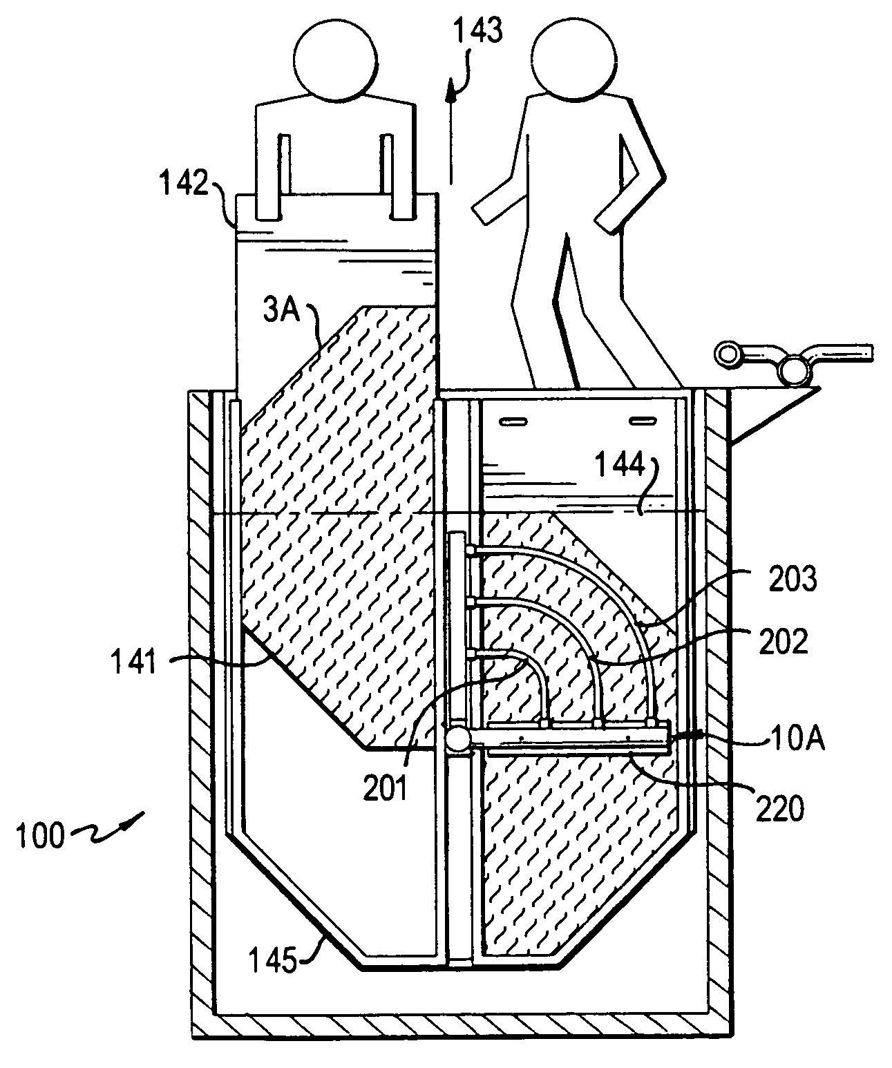
[0038]A detailed view of the invention is disclosed in FIGS. 1-11. The filter apparatus is a filtration device for removing particles from a liquid. The apparatus may be used as a tertiary filtration system for filtering out such particles following treatment from an industrial or municipal wastewater treatment plant. The device may also be used as a primary filtration system in other capacities.

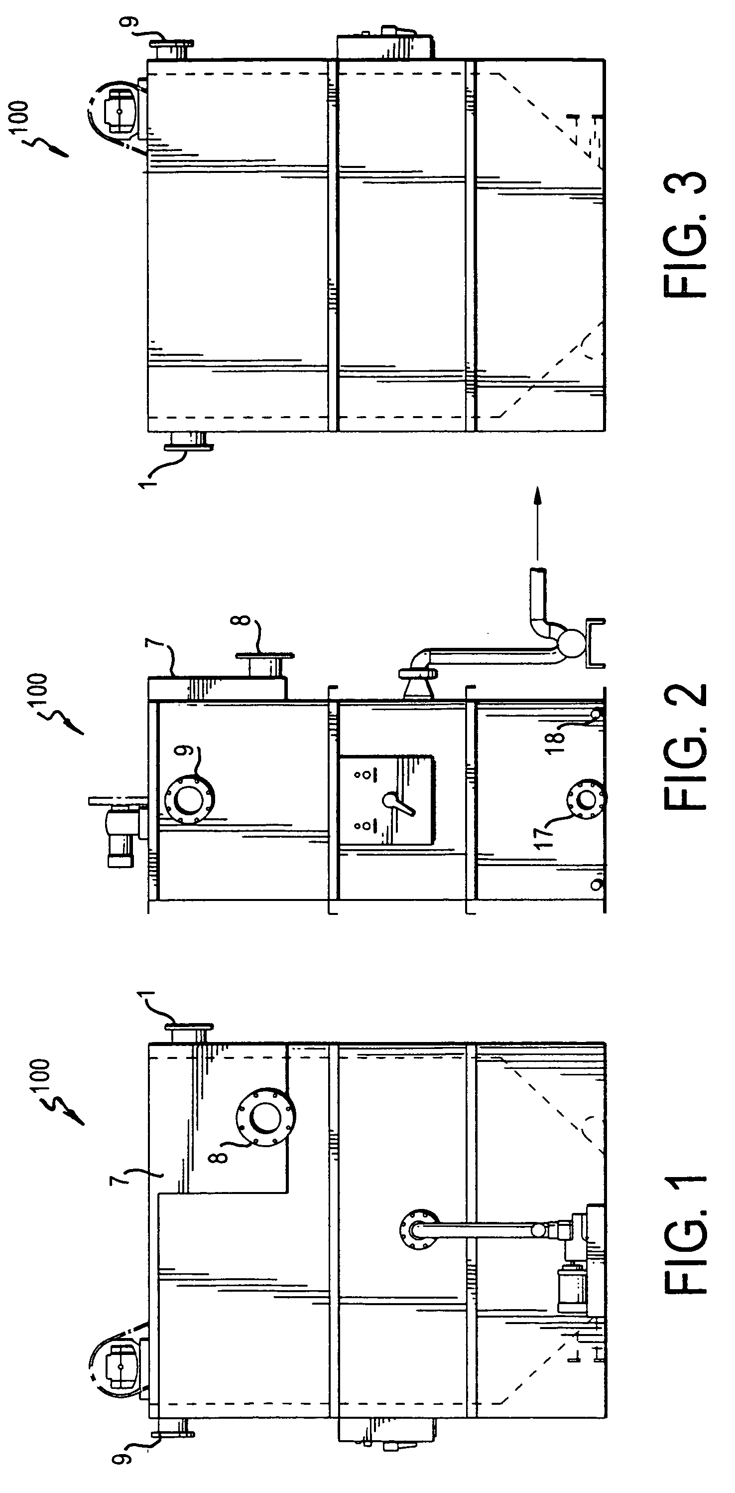
[0039]FIGS. 1-4 show the general features of a filter apparatus 100, which is generally of a box shape comprising several inner compartments. In one embodiment, the liquid to be filtered enters an upper portion of apparatus 100 via an influent pipe 1. Inside the apparatus the liquid is filtered to remove solids from the liquid. The cleaned liquid then passes through a discharge box 7 and is discharged through a discharge pipe 8.

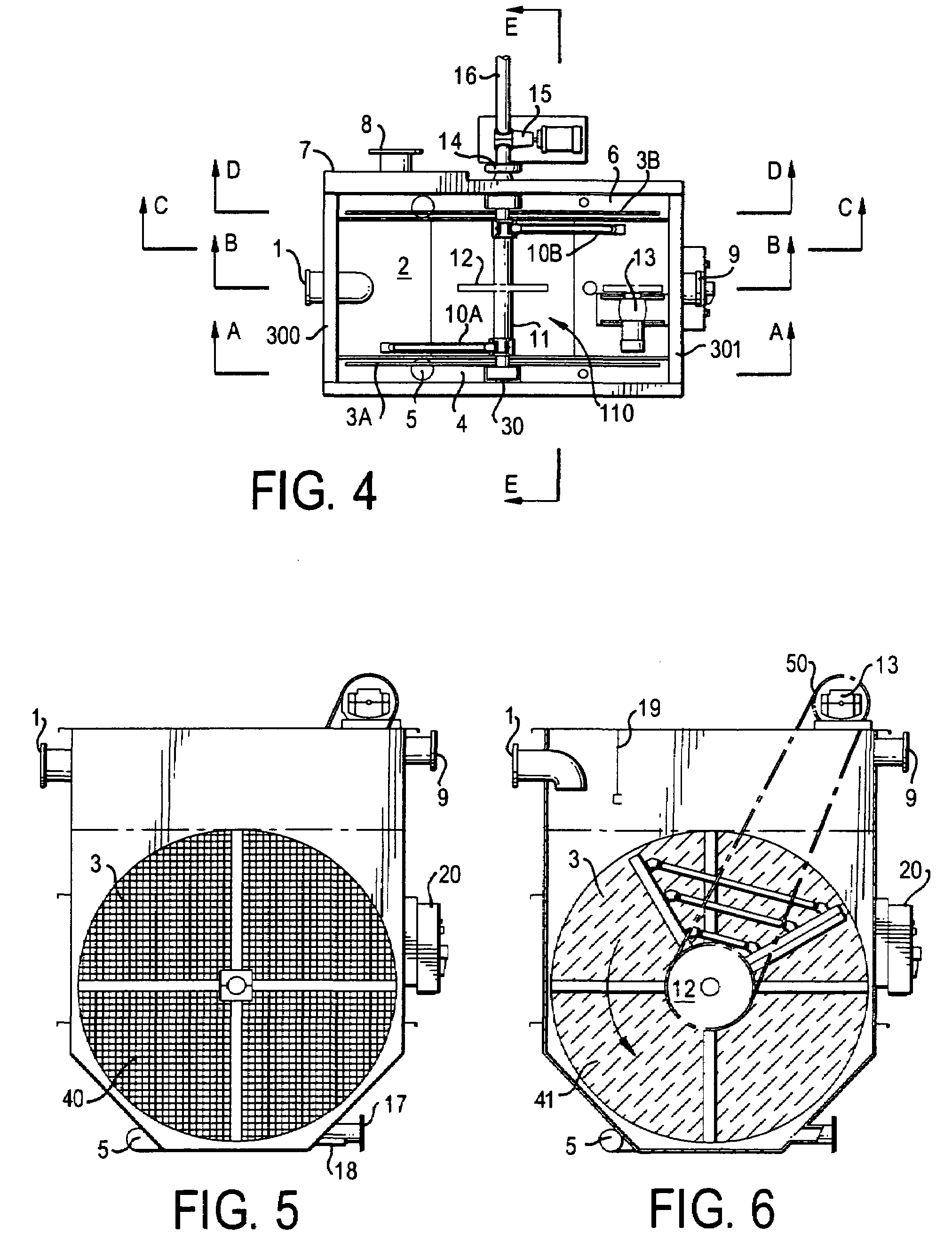
[0040]As shown in FIG. 4, apparatus 100 is divided into three compartments, a dirty liquid chamber 2 and two clean liquid chambers 4 and 6. A transfer pipe 5 intercon...

second embodiment

[0064]the invention is shown in FIGS. 12 and 13. The invention has generally similar operation and components, but has a second filter and wash assembly incorporated therein. In its operation, dirty liquid enters the filter apparatus 600 through influent pipe 601, which is separated and flows into dirty liquid chambers 602A and 602B. Filter assemblies 603A, 603B, 603C and 603D each filter out solids and materials. The clean water flows into clean liquid chambers 604, 604A and 606. The three chambers are connected via a transfer pipe assembly 605, whereby clean liquid flows in order to maintain an equilibrium between them. The clean water then rises and flows out of the filter apparatus through a effluent pipe 608. However, the embodiment of the invention is not limited to that shown in FIGS. 12 and 13 but can be extended further as shown in FIG. 15 to include any number of additional filtering units.

[0065]Wash assembly 710 has a similar appearance and function as disclosed in the pr...


PUM

PropertyMeasurementUnit
lengthaaaaaaaaaa
widthaaaaaaaaaa
sizesaaaaaaaaaa

Abstract

An apparatus for filtering suspended solids from a liquid having a group of filters mounted inside a filter chamber. The filters divide the chamber into dirty liquid chambers and clean liquid chambers. A wash assembly is disposed within the chamber having vacuum / pump heads in contact with the filters rotates within the chamber. The vacuum / pump heads are connected to a pump and vacuum source located either within or without the apparatus. The vacuum / pump heads either vacuum material up or spray material therefrom in order to clean the filters. As the wash assembly rotates, the vacuum heads are able to contact and clean the entire surface of the filters. The filters are reasonably mounted in the chamber such that they may be removed from the chamber for servicing / replacement without the need to drain the chamber or enter the chamber.

Description

CROSS-REFERENCE TO RELATED APPLICATIONS[0001]This application is a continuation-in-part of U.S. Ser. No. 10 / 338,704, filed Jan. 9, 2003, now abandoned, the entire disclosure of which is hereby incorporated by reference.FIELD OF THE INVENTION[0002]This invention relates to an apparatus for filtration of material, such as suspended solids, from a liquid effluent.BACKGROUND OF THE INVENTION[0003]Various filtration apparatus is known in the art. For example, U.S. Pat. Nos. 4,090,965 and 4,639,315, both to Fuchs disclose apparatus whereby a cloth is mounted on a rotatable drum filter on a filter frame. The filter frame defines a boundary between influent and effluent compartments. During filtering, liquid influent containing suspended solids is passed into the influent compartment and flows in a filter direction through the filter into the filter effluent compartment for discharge to an outlet. Intermittent backwashing of the filter material is effected by moving the filter material past...

Claims


Application Information

Patent Timeline
Patent Type & Authority Patents(United States)
IPC IPC(8): B01D35/16B01D29/68B01D29/05B01D29/23
CPCB01D29/05B01D29/23B01D29/54B01D29/6446B01D2201/082
Inventor RICKETTS, DONALD D.
Owner NEXOM US INC
Why Eureka
Try Eureka