Geared spinal implant inserter-distractor

a technology of inserter and distractor, which is applied in the field of spine surgery instruments, can solve the problems of altering the natural separation distance between adjacent vertebrae, degeneration of the intervertebral disc, and deformation of the vertebrae, and achieves the effect of efficient and accurate delivery

Active Publication Date: 2012-02-14
ZIMMER BIOMET SPINE INC
View PDF53 Cites 93 Cited by
  • Summary
  • Abstract
  • Description
  • Claims
  • Application Information

AI Technical Summary

Benefits of technology

[0010]Embodiments disclosed herein provide a surgical instrument that integrates multiple functions to provide the surgical personnel a way to efficiently and accurately deliver an intervertebral implant into a disc space between adjacent vertebrae. More particularly, embodiments disclosed herein provide a geared spinal implant inserter-distractor useful for delivering an intervertebral implant into a collapsed disc space. Embodiments of the geared spinal implant inserter-distractor may be utilized in various surgical procedures, including anterior lumbar interbody fusion (ALIF) via an anterior or anterior-lateral approach, posterior lumbar interbody fusion (PLIF) via a posterior approach, transforaminal lumbar interbody fusion (TLIF) via a posterior-lateral approach, and anterior cervical discectomy and fusion (ACDF), etc.
[0012]Embodiments of a geared spinal implant inserter-distractor disclosed herein further comprise a geared mechanism with gears arranged to translate rotational motion into linear motion, allowing a surgeon to have a greater control and feedback when placing an intervertebral implant within an intervertebral disc space between adjacent vertebrae.
[0014]In some embodiments, a surgeon can turn a knob or crank a handle to drive the inserter component in and out of the distractor component. With the geared mechanism, the rotational motion of turning the knob or cranking the handle can be translated into linear motion in a quantifiable manner, which facilitates the desirable precision delivery of the intervertebral implant to the intervertebral disc space between adjacent vertebrae. The geared mechanism of the geared spinal implant inserter-distractor disclosed herein can also provide the surgical personnel with greater control and feel for the linear movement. By meshing a rack with a pinion, torque can be converted to linear force using less energy, making the geared spinal implant inserter-distractor disclosed herein easy to use.
[0015]In some embodiments, a method of delivering an intervertebral implant in an spinal implant procedure can include fitting a distractor component of a geared spinal implant inserter-distractor in a collapsed disc space between adjacent vertebrae, sliding a collar onto an end portion of an inserter component of the geared spinal implant inserter-distractor, closing inserter tangs at the end portion of the inserter component, placing the inserter tangs inside a hole of the intervertebral implant, spreading the inserter tangs to hold the intervertebral implant by tension, guiding the intervertebral implant, the collar, and the inserter component down the center of the distractor component, and gradually distracting the collapsed disc space between the adjacent vertebrae by applying a controlled rotating force onto a handle or knob of the geared spinal implant inserter-distractor to push the inserter component towards the collapsed disc space in a linear motion. The protruding features of the collar can guide and keep the intervertebral implant in alignment with the distractor component. As the surgical personnel turns the handle or knob, the body portion of the collar can push against the ramps of the distractor component to shield the intervertebral implant from compression loading until the intervertebral implant is delivered in a proper location between the adjacent vertebrae. The intervertebral implant thus delivered can restore lumbar disc height in the treatment of diseased or degenerative discs.
[0016]Embodiments of a geared spinal implant inserter-distractor disclosed herein can provide many advantages. Particularly, embodiments of a geared spinal implant inserter-distractor disclosed herein can overcome problems associated with delivering an implant into a collapsed disc space via impaction or sudden distraction. Impaction or sudden distraction may cause damage or unwanted results. For example, impacting an implant into a collapsed disc space may fracture one or both vertebrae and the implant itself. By gradually delivering an implant via a geared mechanism, embodiments of a geared spinal implant inserter-distractor disclosed herein can avoid risking fracturing the adjacent vertebrae. Moreover, by utilizing a collar in conjunction with the inserter-distractor components, embodiments of a geared spinal implant inserter-distractor disclosed herein can shield an implant from compression loading during delivery.

Problems solved by technology

An intervertebral disc may be subject to degeneration caused by trauma, disease, and / or aging.
Partial or full removal of an intervertebral disc may destabilize the spinal column, resulting in subsidence or deformation of vertebrae.
Moreover, destabilization of a spinal column may result in alteration of a natural separation distance between adjacent vertebrae.
As one skilled in the art can appreciate, excessive pressure applied to the nerves may cause pain and / or nerve damage.

Method used


Image

  • Geared spinal implant inserter-distractor
  • Geared spinal implant inserter-distractor
  • Geared spinal implant inserter-distractor

Examples


Embodiment Construction

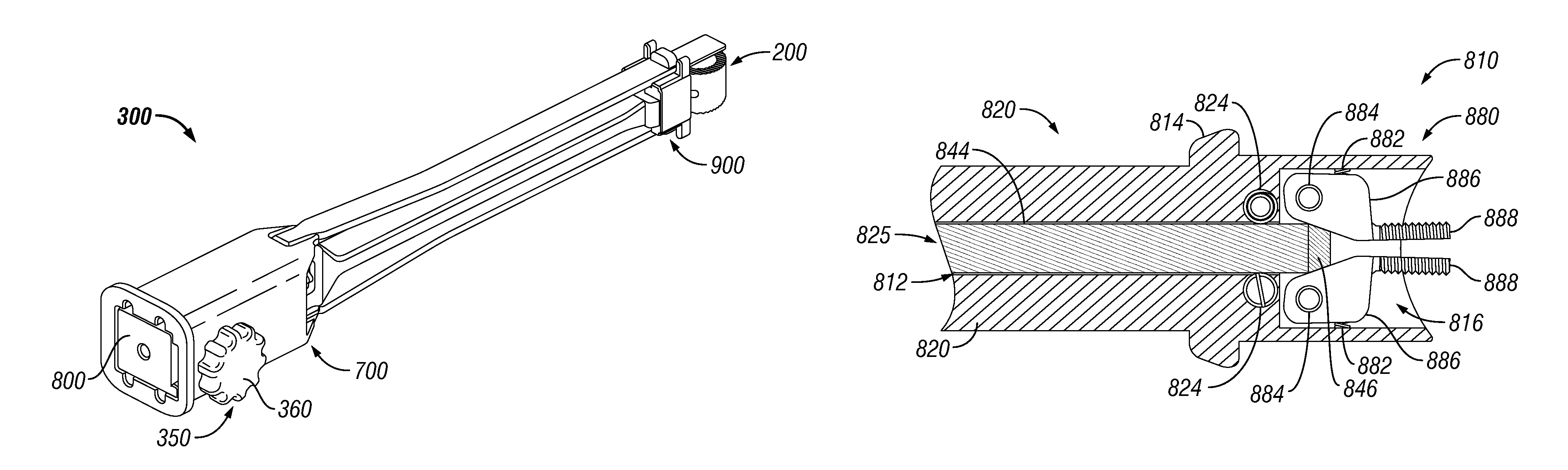
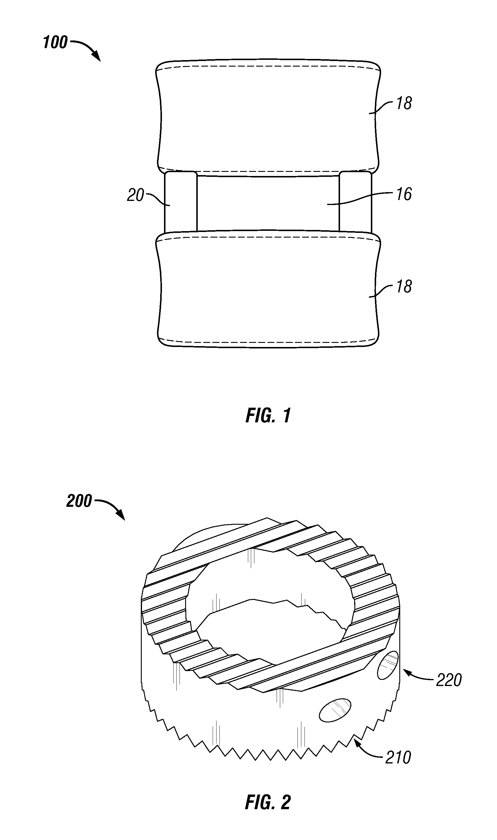
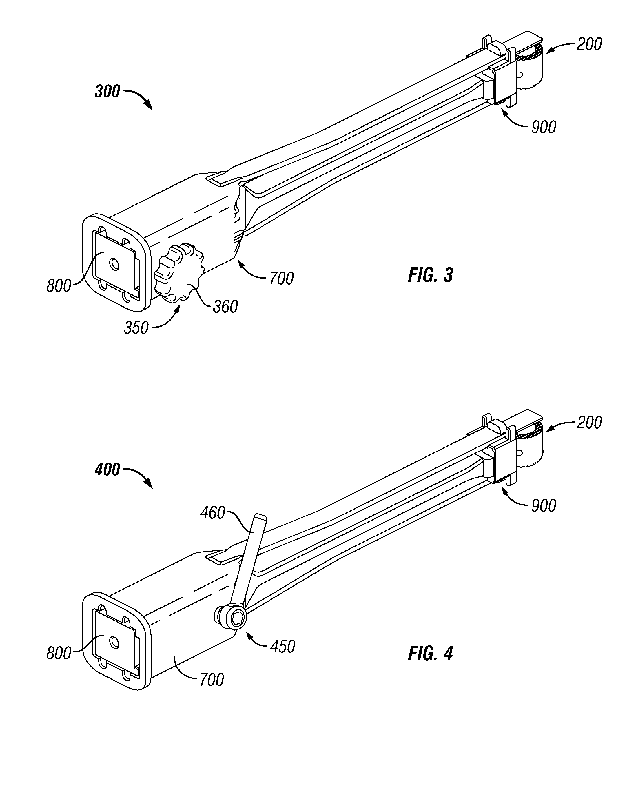
[0032]Embodiments of a geared spinal implant inserter-distractor and the various features and advantageous details thereof are explained more fully with reference to the non-limiting embodiments detailed in the following description. Descriptions of well known starting materials, manufacturing techniques, components and equipment are omitted so as not to unnecessarily obscure the invention in detail. Skilled artisans should understand, however, that the detailed description and the specific examples, while disclosing preferred embodiments of the invention, are given by way of illustration only and not by way of limitation. Various substitutions, modifications, and additions within the scope of the underlying inventive concept(s) will become apparent to those skilled in the art after reading this disclosure. Skilled artisans can also appreciate that the drawings disclosed herein are not necessarily drawn to scale.

[0033]As used herein, the terms “comprises,”“comprising,” includes, “in...


PUM


Abstract

Embodiments of a geared spinal implant inserter-distractor disclosed herein provide a greater mechanical advantage in delivering an intervertebral implant via an anterior, anterior-lateral, or posterior approach. The geared spinal implant inserter-distractor comprises an inserter, a distractor structured to slidably receive the inserter with a collar and an intervertebral implant attached thereto, and a gear mechanism arranged to translate a surgeon's rotational motion into linear motion, allowing the surgeon to have a greater control and feedback when placing an implant within an intervertebral disc space. The gear arrangement comprises a pinion inside the distractor and a rack on the inserter. The pinion can be driven by a shaft connected to a knob or handle. With the gear mechanism, a surgeon can turn the knob or handle to drive the inserter in and out of the distractor in a quantifiable manner, which facilitates the desirable precision delivery of the intervertebral implant.

Description

TECHNICAL FIELD OF THE DISCLOSURE[0001]Embodiments of the disclosure relate generally to instruments for spine surgery. More particularly, embodiments of the disclosure relate to an implant inserter-distractor instrument useful for delivering an interbody device. Even more particularly, embodiments of the disclosure relate to a geared spinal implant inserter-distractor for delivering a bone graft via an anterior, anterior-lateral, or a posterior approach.BACKGROUND OF THE RELATED ART[0002]The human spine consists of segments known as vertebrae linked by intervertebral disks and held together by ligaments. There are 24 movable vertebrae—7 cervical (neck) vertebrae, 12 thoracic (chest) vertebrae, and 5 lumbar (back) vertebrae. Each vertebra has a somewhat cylindrical bony body (centrum), a number of winglike projections (processes), and a bony arch. The arches are positioned so that the space they enclose forms the vertebral canal. The vertebral canal houses and protects the spinal co...

Claims


Application Information

Patent Timeline
Patent Type & Authority Patents(United States)
IPC IPC(8): A61B17/58A61F2/44
CPCA61F2/4465A61F2/4611A61B2017/0256A61F2002/4475A61F2002/4628A61F2002/30593
Inventor MILLER, PETER THOMAS
Owner ZIMMER BIOMET SPINE INC
Why Eureka
Try Eureka