System and method for flicker detection in digital imaging

a digital imaging and detection system technology, applied in the field of imaging systems, can solve the problems of flicker, flicker, flicker, etc., and achieve the effect of magnifying the effect of flicker in image data

Active Publication Date: 2009-05-26
NXP USA INC
View PDF20 Cites 12 Cited by
  • Summary
  • Abstract
  • Description
  • Claims
  • Application Information

AI Technical Summary

Benefits of technology

[0009]In one embodiment, the frame-to-frame comparison is performed using multiple patterns of alternating sign weights signs having different relative phases. For example, the comparison uses two patterns of alternating sign weights 90 degrees out of phase with each other. This improves the ability to detect flicker by increasing the probability that flicker in the image will occur in phase with at least one of the patterns of alternating sign weights.

Problems solved by technology

Because there is a time delay in the image acquisition between one row of the image pixels and a subsequent row, there may have been a change in the actual light level, causing unwanted variability in the image.
One type of unwanted variability that can be present in a digital image quality is flicker.
In a digital camera, flicker can be caused by the fluctuation in light provided by common light sources.
However, these fluctuations can interact with the digital camera timing due to the rolling shutter in the CMOS sensor, resulting in noticeable variability in the digital image.
Furthermore, in a live-view image, the rolling of these bars causes apparent flicker of the entire image.
Unfortunately, previous methods of flicker detection have had limited reliability and / or have required large amounts of computing resources.

Method used


Image

  • System and method for flicker detection in digital imaging
  • System and method for flicker detection in digital imaging
  • System and method for flicker detection in digital imaging

Examples


Embodiment Construction

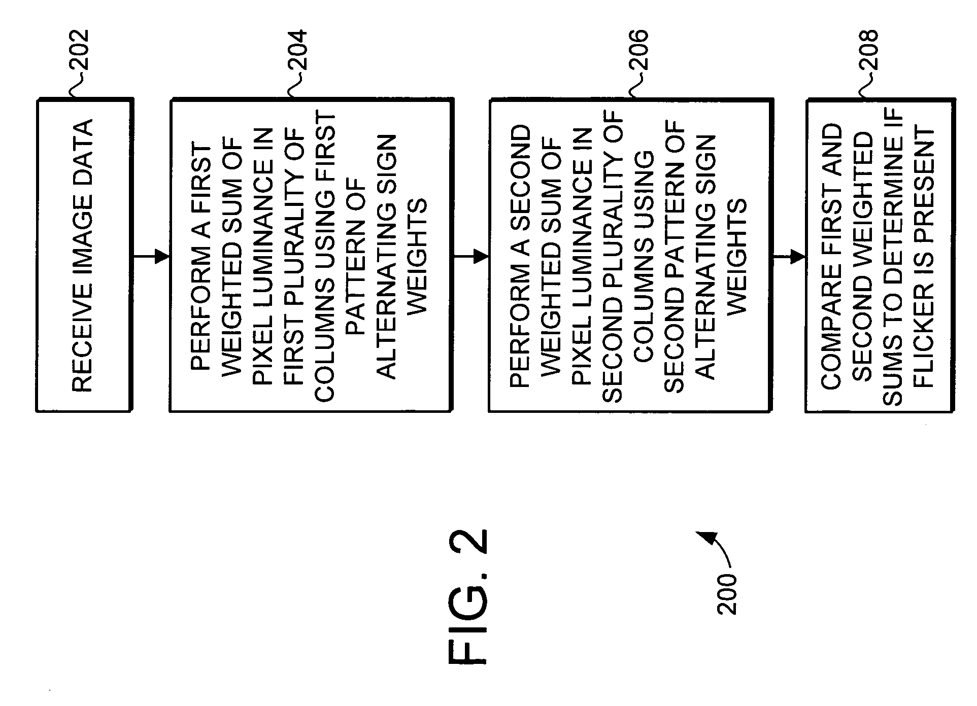
[0017]The present invention provides a system and method for detecting flicker in a digital image. The system and method detects flicker by performing a frame-to-frame, column-to-column, and row-to-row comparison of image data. The frame-to-frame comparison of image data is based on dividing each image into multiple columns, and performing a weighted sum of the pixel luminance in each column using a pattern of alternating sign weights for different rows.

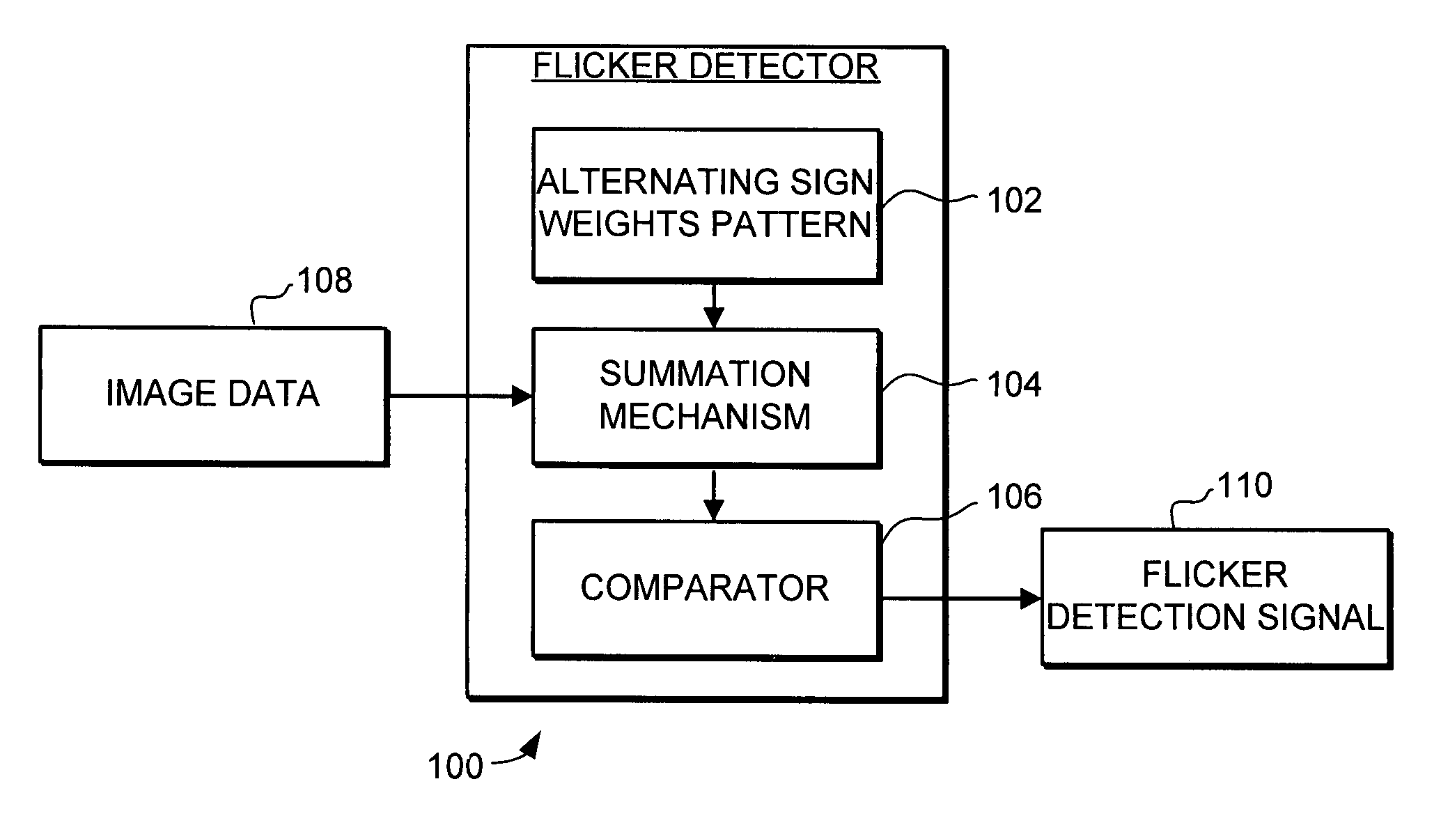
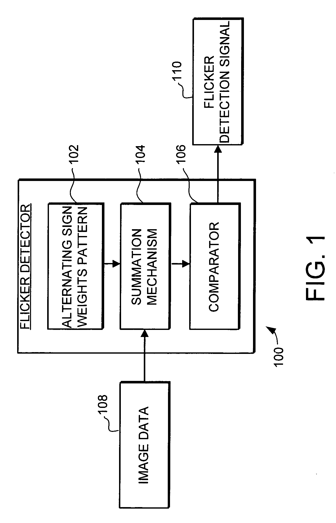
[0018]Turning now to FIG. 1, a flicker detector 100 in accordance with an embodiment of the invention is illustrated schematically. The flicker detector 100 includes an alternating sign weights pattern 102, a summation mechanism 104, and a comparator 106. The flicker detector 100 receives image data from the camera, with that image data including rows of pixel luminance data. The summation mechanism 104 and the alternating sign weights pattern 102 are used to sum the pixel luminance for each column in the image, with the sign applied...


PUM


Abstract

A system and method for detecting flicker in a digital image. The system and method detects flicker by performing a frame-to-frame comparison of image data. The frame-to-frame comparison of image data is based on dividing each image into multiple columns, and performing a weighted sum of the pixel luminance in each column using a pattern of alternating sign weights. The weighted sum of luminance for each column in a first frame is compared to the weighted sum of luminance for that column in a second frame to determine if there is a simultaneous luminance variation in those columns. For example, if the difference between weighted sums of luminance between frames exceeds a threshold value in a predetermined number of columns then there is a simultaneous luminance variation in those columns, and a horizontal pattern of flicker has been detected in the image data.

Description

FIELD OF THE INVENTION[0001]This invention generally relates to imaging systems, and more specifically relates to digital imaging.BACKGROUND OF THE INVENTION[0002]Digital imaging systems have created a revolution in photography and cameras. A digital camera is similar to a film camera except that the film is replaced with an electronic sensor. The sensor is comprised of an array of photo detectors that change the photons that strike them into electrons providing a signal at each pixel proportional to the number of photons, or the amount of light at each pixel. Presently, most consumer digital cameras employ Charge Coupled Device (CCD) or Complementary Metal Oxide Semiconductor (CMOS) sensors. To facilitate the collection of light, many of the sensors employ a small lens-like structure covering each pixel, which is called a microlens. These microlenses are typically made by forming a layer of photoresist that is placed upon the pixel frame.[0003]When subjected to light, the image sen...

Claims


Application Information

Patent Timeline
Patent Type & AuthorityPatents(United States)
IPC IPC(8): H04N9/73
CPCH04N5/2351H04N5/2357H04N23/71H04N23/745
InventorYANOF, ARNOLD W.
OwnerNXP USA INC