Footwear article with adjustable stiffness
a technology of adjustable stiffness and footwear, applied in the field of footwear, can solve the problems of inability the same boots/shoes may not be properly adapted for driving or walking to the jobsite, and the same boots/shoes may not be able to provide the most desirable comfort to the wearer, etc., to achieve the effect of increasing the comfort of the wearer of the footwear
- Summary
- Abstract
- Description
- Claims
- Application Information
AI Technical Summary
Benefits of technology
Problems solved by technology
Method used
Image
Examples
seventh embodiment
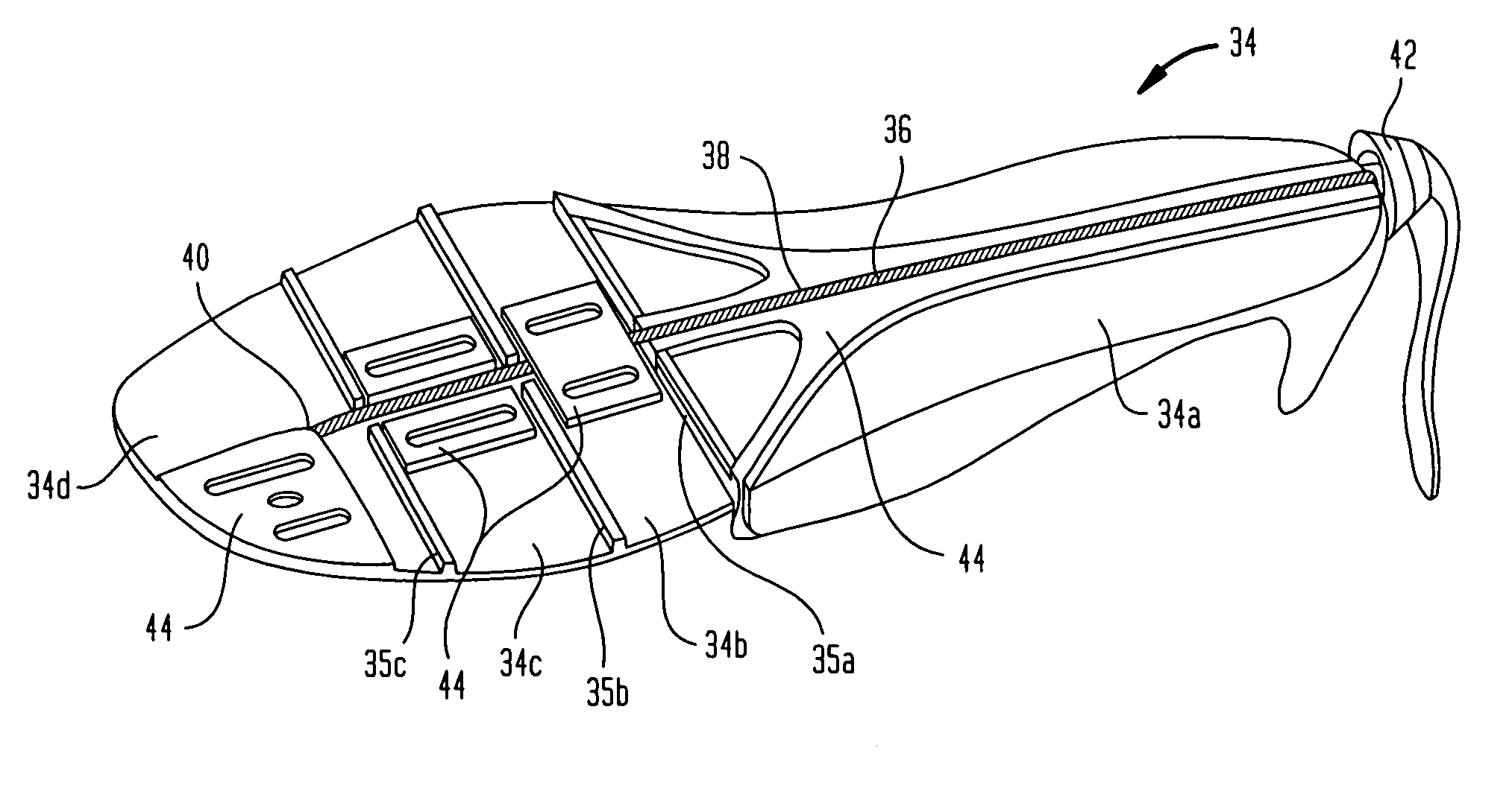
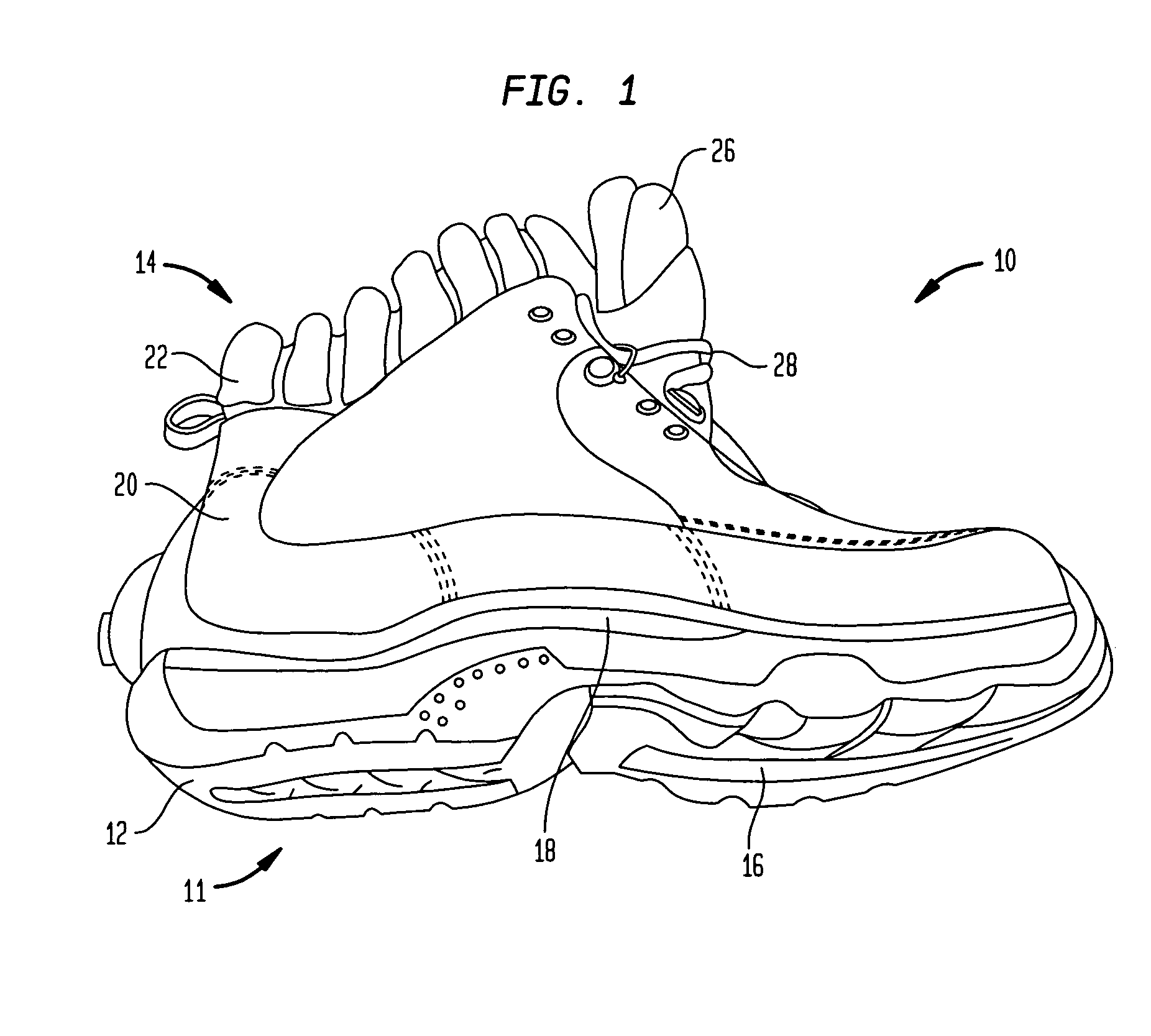
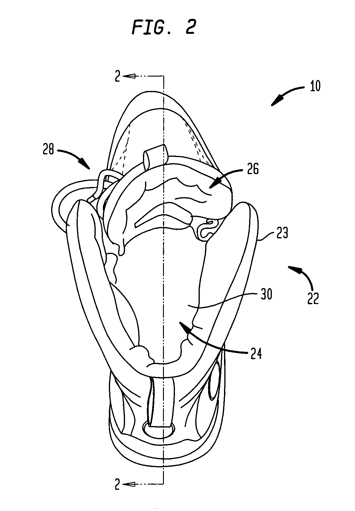
[0042]As best shown in the partial cross sectional view of FIG. 3, shoe 10 also includes a component 32, such as an adjustable shank, which may be a variety of different designs that include different elements. Certain of these designs will be discussed further below, with the general adjustable shank element being consistently referred to throughout with reference numeral 32. The exemplary adjustable shank depicted in FIG. 3 is denoted with general reference numeral 32, and is further discussed below in reference to a In accordance with the present invention, adjustable shank 32 is designed so as to vary the stiffness of sole unit 11 of shoe 10. Thus, the above discussed shortcomings of regular shoes, with regard to sole stiffness, may be avoided and the comfort of the wearer improved. In its most general form, shank 32 may include one or more elements or segments which are capable of being manipulated to change a stiffness property of sole unit 11, and thereby the flexibility of ...
first embodiment
[0051]In this first embodiment, adjustable shank 32 also preferably includes a tension cable 36. As shown in FIG. 4A, tension cable 36 may be situated so as to extend along an approximate midline of plate 34, across or through each segment 34n, while at the same time crossing over each flex point 35m. However, it is clearly envisioned to situate cable 36 in any other position across any of the provided segments and / or flex points. In a most preferred embodiment shown in the figures, cable 36 is arranged in a channel 38 or the like formed in and across segments 34a, 34b, 34c and 34d and flex points 35a, 35b and 35c. However, a channel such as this is not necessary. In a preferred embodiment, cable 36 is constructed of steel braided cable, but may be may other types of material suitable for use with plate 34. For example, cable 36 can be made of any suitable material that is strong enough to provide the necessary resistance in the operation of shank 32. Such suitable materials could i...
second embodiment
[0058]In accordance with this second embodiment, it is envisioned to provide individual separate perimeter cables 137a and 137b, or to provide one cable that extends around plate 134. In the latter case, the respective ends of the single cable would be connected or otherwise mechanically coupled with and operated by handle 142. In addition, it is noted that handle 142 may be adapted to adjust all of the cables at the same time, or individually. For example, in the case of three separate cables 136, 137a and 137b, handle 142 may be adapted to provide / release tension with one motion. Alternatively, the handle may include a selector or the like for determining which cable is to be manipulated.
[0059]Yet another embodiment of the adjustable shank 32 is depicted in FIG. 7. Once again, like elements to those of the first embodiment will be labeled with similar reference numerals, but within the 200-series of numbers. For example, in this third embodiment, adjustable shank 32 comprises a pl...
PUM
| Property | Measurement | Unit |
|---|---|---|
| stiffness | aaaaa | aaaaa |
| stiffness/flexibility | aaaaa | aaaaa |
| flexibility | aaaaa | aaaaa |
Abstract
Description
Claims
Application Information
 - R&D
- Intellectual Property
- Life Sciences
- Materials
- Tech Scout
- Unparalleled Data Quality
- Higher Quality Content
- 60% Fewer Hallucinations
Browse by: Latest US Patents, China's latest patents, Technical Efficacy Thesaurus, Application Domain, Technology Topic, Popular Technical Reports.
© 2025 PatSnap. All rights reserved.Legal|Privacy policy|Modern Slavery Act Transparency Statement|Sitemap|About US| Contact US: help@patsnap.com


