Flip top cap

a top cap and flip technology, applied in the field of flip top caps, can solve the problems of reducing the possibility of contact with the open top of the vessel, and achieve the effects of facilitating threaded mounting of the body, facilitating digital manipulation of the lid, and facilitating gripping and rotation of the body

Active Publication Date: 2009-06-16
CORNING INC
View PDF41 Cites 23 Cited by
  • Summary
  • Abstract
  • Description
  • Claims
  • Application Information

AI Technical Summary

Benefits of technology

[0011]The lid of the cap may be joined to a body and the body may be mounted to the open top of the vessel. For example, the vessel may include an array of threads, and the body may include an array of mating threads for securely mounting the body to the vessel. The exterior of the body may be configured to facilitate threaded mounting of the body on the vessel. For example, the body may have ribs that extend parallel to the axis about which the threads are generated. Alternatively the exterior of the body may have bumps, depressions, roughening or other surface irregularities to facilitate gripping and rotation of the body relative to the vessel. The body and the lid may be joined unitarily to one another by a living hinge. The living hinge may be an over-center hinge that is biased towards a fully closed position and / or a fully opened position. Thus, the over-center hinge will assist complete opening and / or complete closing of the lid.
[0012]The lid preferably includes at least one external surface configuration to facilitate digital manipulation of the lid. At least part of the external surface configuration preferably is offset from a line that passes perpendicular to the rotational axis of the hinge at a location centrally along the hinge. The offset positioning of the external surface configuration offsets the thumb or forefinger of the user from the open top of the vessel, and hence reduces the possibility of contact with the open top of the vessel. Hence, the potential for contamination of cell or tissue cultures in the vessel is reduced. The external surface configurations can include ribs, tabs, bumps, depressions, textures or other such configurations on the lid to facilitate opening.
[0013]The lid preferably includes a shield disposed to at least partly surround the open top of the vessel when the lid is in the closed position. The shield is at a side of the lid opposite the hinged connection and preferably extends along at least portions of the lid that have the external surface configuration to facilitate opening. More particularly, the shield preferably is disposed between the vessel and the external surface configuration on the lid. Accordingly, the shield helps to prevent contact with the open top of the vessel as the lid is being opened by a thumb or forefinger. The shield also prevents contact with portions of the lid that seal the open top.
[0014]The lid may further include a skirt dimensioned to telescope into the open top of the vessel or into the open top of the body mounted to the vessel. The skirt is dimensioned for sealed engagement with the open top of the vessel or with the body to achieve sterile containment of cell or tissue cultures in the vessel. Outer circumferential portions of the skirt may include anti-splash features, such as notches. The notches or other such anti-splash features balance air pressure between the inside and the outside of the vessel during the initial stage of opening the lid, and hence reduce the possibility of spraying or splashing as the lid is opened. The shield and the tab are disposed to prevent inadvertent contact with the skirt while the lid is being opened.

Problems solved by technology

The offset positioning of the external surface configuration offsets the thumb or forefinger of the user from the open top of the vessel, and hence reduces the possibility of contact with the open top of the vessel.

Method used


Image

  • Flip top cap
  • Flip top cap
  • Flip top cap

Examples


Embodiment Construction

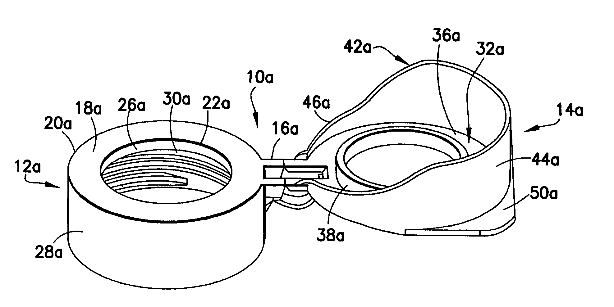
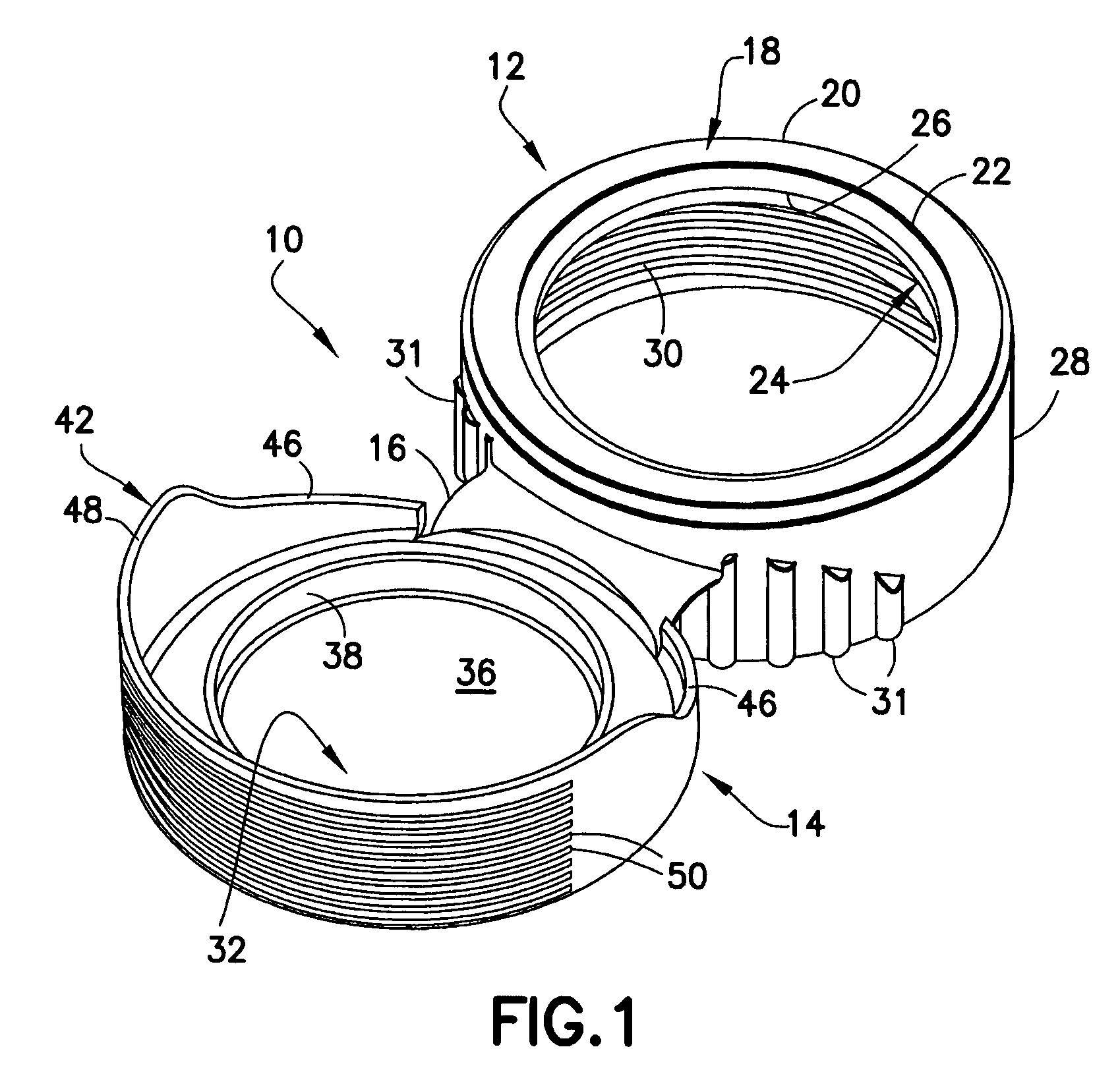
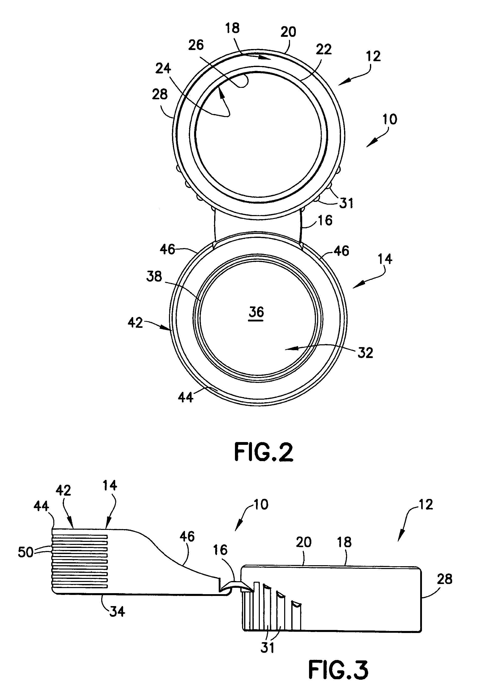
[0030]A cap in accordance with a first embodiment of the invention is identified generally by the numeral 10 in FIGS. 1-9. Cap 10 is molded unitarily from resin and includes a body 12 and a lid 14 that are joined unitarily by a living hinge 16. Hinge 16 enables lid 14 to be rotated approximately 180° between a fully open position, as shown in FIGS. 1-3, and a fully closed position, as shown in FIGS. 4-6. Additionally, hinge 16 has an over-center design configured to bias lid 14 through the final stages of rotation towards the open position of FIGS. 1-3 and through the final stages of rotation towards the closed open position of FIGS. 4-7.

[0031]Body 12 includes a generally planar top wall 18 with a circular outer periphery 20 and a circular opening 22 concentric with outer periphery 20. A short cylindrical inner wall 24 extends down from top wall 18 concentrically with circular opening 22 in top wall 18. Thus, circular opening 22 and inner wall 24 define a short cylindrical sealing s...


PUM


Abstract

A cap is provided for a laboratory vessel. The cap includes a lid that can be rotated relative to the laboratory vessel from a closed position to an open position. The lid includes a shield for at least partly surrounding the open top of the laboratory vessel. Ribs are disposed on outer surfaces of the shield for receiving manual digital pressure for opening and / or closing the lid.

Description

BACKGROUND OF THE INVENTION[0001]1. Field of the Invention[0002]The invention relates to a flip top cap for use with laboratory vessels, such as tubes.[0003]2. Description of the Related Art[0004]Many laboratory procedures require tissue cultures or cell cultures to be stored and / or cultivated in a vessel, such as a tube or a flask. The typical tube includes a cylindrical side wall, a closed bottom and an open top. The closed bottom often is conically generated. The size of the tube varies from one laboratory procedure to another, and tubes typically will define volumes from 15 mL to 50 mL. Flasks also have a side wall, a closed bottom and an open top. For simplicity, the following discussion will describe tubes, but pertains to other laboratory vessels as well.[0005]Many laboratory procedures require the tissue or cell cultures in the tube to remain sterile. Thus, the tube typically is provided with a cap for sealing the open top of the tube. However, the cap must be removed period...

Claims


Application Information

Patent Timeline
Patent Type & Authority Patents(United States)
IPC IPC(8): B65D51/16B65D51/18B65D41/00
CPCB01L3/50825B01L2200/141B01L2300/043
Inventor GIUSTI, DAVID C.
Owner CORNING INC
Why Eureka
Try Eureka