Check patentability & draft patents in minutes with Patsnap Eureka AI!

Imaging processing device and a method of processing an image

a processing device and image technology, applied in the field of image processing devices and methods, can solve the problems of not being able to pick up image signals the shutter speed and aperture control cannot follow the speed of adjustment of light sources, and the image in a normal state cannot be picked up

Inactive Publication Date: 2009-07-07
FUJITSU GENERAL LTD
View PDF9 Cites 10 Cited by
  • Summary
  • Abstract
  • Description
  • Claims
  • Application Information

AI Technical Summary

Benefits of technology

[0013]An operation supporting system according to still another aspect of the present invention include an image obtaining unit that obtains an image picked up by an imaging unit; an exposure controller that in an exposure control period automatically controls an exposure of the imaging unit based on a density distribution of an image obtained by the image obtaining unit, wherein the exposure control period includes at least a maximum exposure period during which the exposure is set to a maximum exposure, a minimum exposure period during which the exposure is set to a minimum exposure, and a normal exposure period during which the exposure is set to in between the maximum exposure and the minimum exposure; a determining unit that determines any one of whether the imaging unit is abnormal and whether environment is unsuitable for picking up an image by the imaging unit based on densities of images that are picked up during the maximum exposure period, the minimum exposure period, and / or the normal exposure period; and a supporting unit that controls operation of a vehicle using at least the image or provides information to a driver, thereby supporting running of a vehicle.

Problems solved by technology

However, sometimes the shutter speed and the aperture control cannot follow the speed of adjustments of the light source.
When the camera control cannot follow the speed of changes in light source conditions or when a bright density loss or a dark density loss occurs in picked-up images that is beyond control of the camera, the picked-up image signals cannot be processed properly.
However, if the camera is down, an image in a normal state cannot be picked up.
However, it is not possible to determine whether the luminance signal of a preset clip level or higher is due to a temporary environmental change or due to a trouble in the camera itself.

Method used


Image

  • Imaging processing device and a method of processing an image
  • Imaging processing device and a method of processing an image
  • Imaging processing device and a method of processing an image

Examples


first embodiment

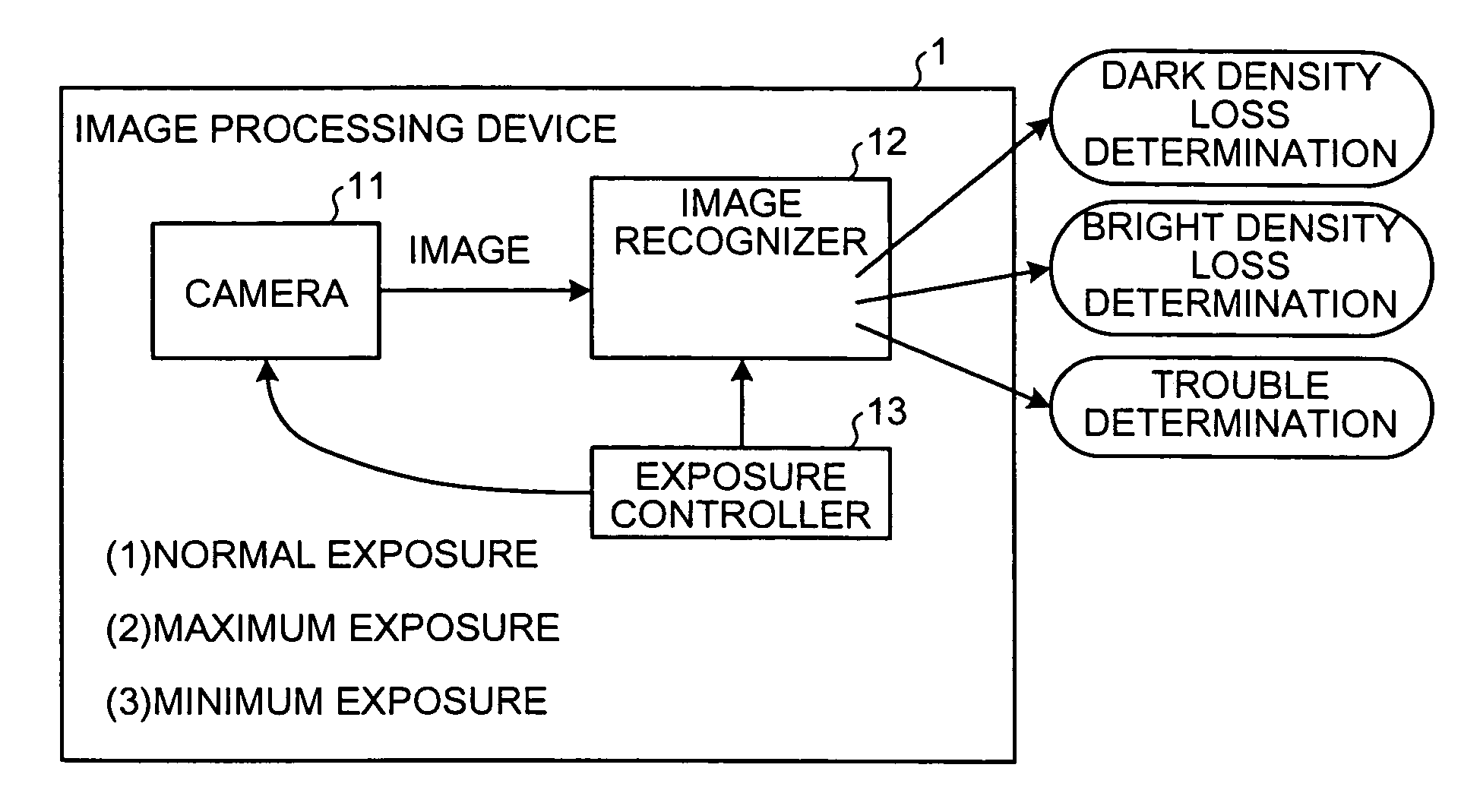
[0040]The monitor 14 displays an image obtained from the image data processed by the image recognizer 12. When the trouble determining unit 15 determines that the camera 11 has trouble, the alarm unit 16 notifies the user of the image processing device 1 about the trouble in the camera 11 using an alarm lamp, an alarm sound, or an alarm display. While the monitor 14 and the alarm unit 16 are separately provided the monitor 14 may include the alarm unit 16.

[0041]A relationship between a gradation of an image recognized by the image recognizer shown in FIG. 2 and the number of pixels in each gradation is explained next. FIG. 3 to FIG. 5 are density histograms. A density histogram is a luminance distribution of an image. The abscissa axis represents a gradation of density that indicates brightness of image data converted into a digital value. The gradation is expressed in 0 (black) to 255 (white), for example. The ordinate axis represents the number of pixels corresponding to a densit...

second embodiment

[0106]An image processing device 2 is shown in FIG. 10. The image processing device 2 includes a trouble determination timing changer 21. The trouble determination timing changer 21 receives a control signal from the outside, and controls the operation of an exposure controller 23, that is, changing of a normal exposure, a maximum exposure, and a minimum exposure. The trouble determination timing changer 21 notifies an image recognizer 22 about a timing at which a maximum exposure and a minimum exposure are inserted.

[0107]The image recognizer 22 uses an obtained image for the trouble determination by the trouble determining unit 15 based on the notification from the trouble determination timing changer 21. The image recognizer 22 carries out a predetermined processing to a picked-up normal exposure image and outputs a processed result to the outside, and outputs a result of a determination made by the trouble determining unit 15 to the outside.

[0108]Other configurations and the ope...


PUM


Abstract

An image processing device includes a camera that picks up an image, an image density recognizer that recognizes density of the image, and an exposure controller that in an exposure control period automatically controls an exposure of the camera based on the density recognized. The exposure controller period includes at least a maximum exposure period during which the exposure is set to a maximum exposure, a minimum exposure period during which the exposure is set to a minimum exposure, and a normal exposure period during which the exposure is set to in between the maximum exposure and the minimum exposure.

Description

BACKGROUND OF THE INVENTION[0001]1) Field of the Invention[0002]The present invention relates to a technology for determining a cause of an inability of processing a picked-up image.[0003]2) Description of the Related Art[0004]Some of the techniques that have been developed recently enable preventing running vehicles getting into accidents and assisting running and parking of the vehicles. According to these techniques, an imaging device is installed on a vehicle, and image information is collected with the imaging device on the surrounding of the vehicle while the vehicle is running. The image information is processed and used to predict accidents and prevent the vehicle getting into the accident. The imaging device is generally a camera. The amount of light that enters the cameras changes with brightness of the sun, climate, and shadows of objects so that a light source in the camera continuously adjusts itself accordingly. However, sometimes the shutter speed and the aperture con...

Claims


Application Information

Patent Timeline
Patent Type & Authority Patents(United States)
IPC IPC(8): H04N5/235G03B7/00H04N5/238B60R1/00G03B7/089G06T1/00G08G1/16H04N5/225H04N5/232
CPCH04N5/232H04N5/2353H04N5/235H04N23/634H04N23/73H04N23/70
Inventor HONDA, KANAKO F.SHIMA, NOBUKAZU
Owner FUJITSU GENERAL LTD
Features
  • R&D
  • Intellectual Property
  • Life Sciences
  • Materials
  • Tech Scout
  • Unparalleled Data Quality
  • Higher Quality Content
  • 60% Fewer Hallucinations
Learn More