
Harvesting energy from flowing fluid

a technology of flowing fluid and energy, applied in the field of harvesting energy, can solve problems such as problems such as problems such as problems such as electrical generators and easy failure of moving parts, and achieve the effects of less secure anchoring, less deformation and electrical energy production, and more controllable and predictable energy

Active Publication Date: 2009-07-14
SCHLUMBERGER TECH CORP
View PDF34 Cites 40 Cited by
  • Summary
  • Abstract
  • Description
  • Claims
  • Application Information

AI Technical Summary

Benefits of technology

The device generates continuous electrical energy from fluid flow, reducing the risk of moving part failure and turbulence dependency, offering predictable and controlled energy production in harsh environments.

Problems solved by technology

The a harsh downhole environment, moving parts are apt to fail.
An electrical generator may be problematic in a harsh downhole environment because it has relatively numerous moving parts which are prone to failure, including bearings and shaft seals.

Method used


Image

  • Harvesting energy from flowing fluid
  • Harvesting energy from flowing fluid
  • Harvesting energy from flowing fluid

Examples


Embodiment Construction

[0033]The particulars described herein are by way of example for purposes of discussion of the illustrated embodiments of the present invention in order to provide what is believed to be a useful and readily understood description of the principles and conceptual aspects of the invention. No attempt is made to show structural aspects of the invention in more detail than is necessary for a fundamental understanding of the invention.

[0034]The invention may be implemented in various different embodiments of a device for converting kinetic energy from the surrounding environment into electrical energy. The embodiments are described below in the context of the source of kinetic energy being fluid flow through a borehole such as those associated with petrochemical wells. However, the invention is not limited to petrochemical wells.

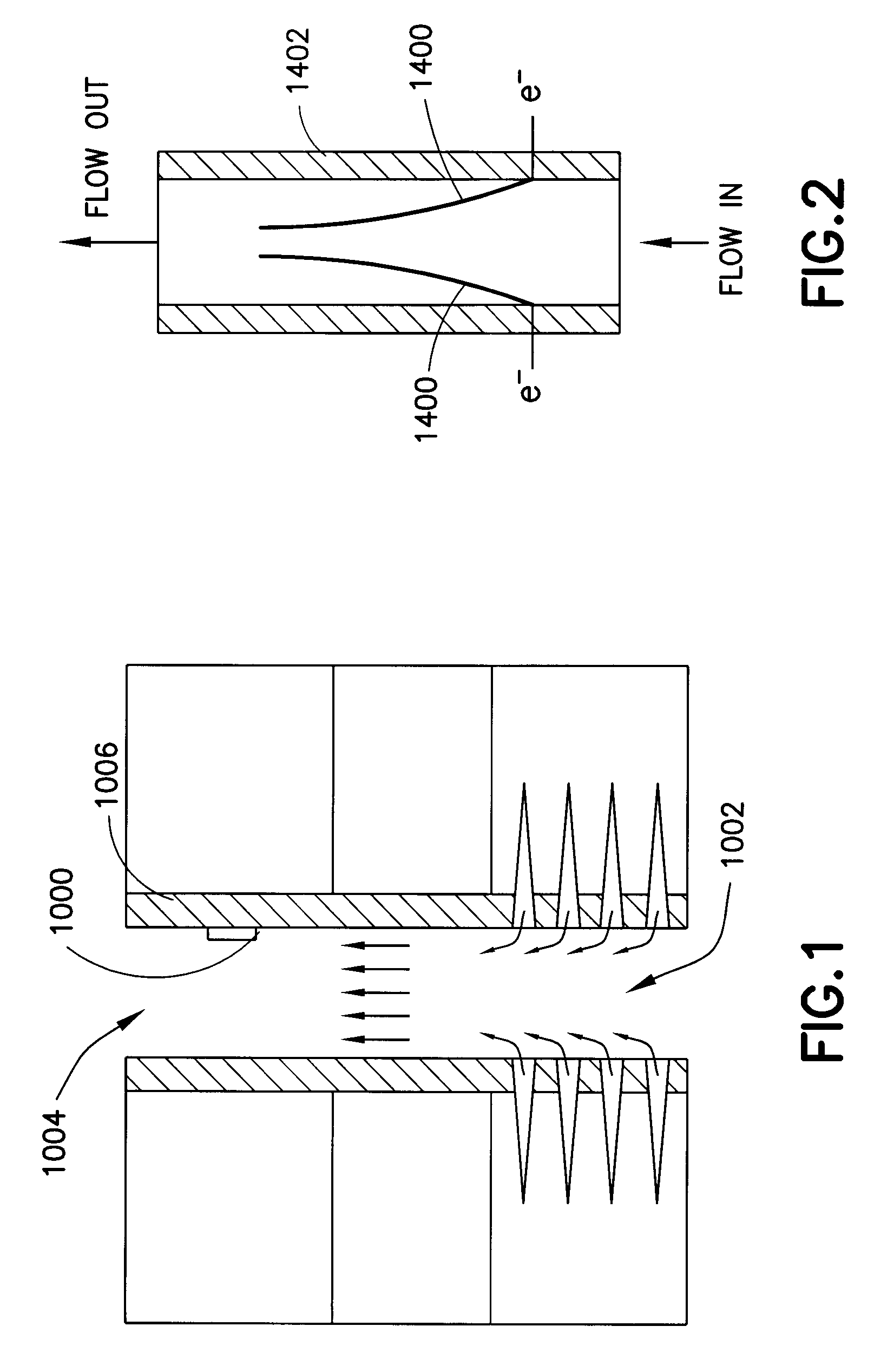
[0035]Referring to FIGS. 1 through 3, an energy harvesting device (1000) converts the kinetic energy of a fluid flow (1002) in a borehole (1004) into electrical...


PUM


Abstract

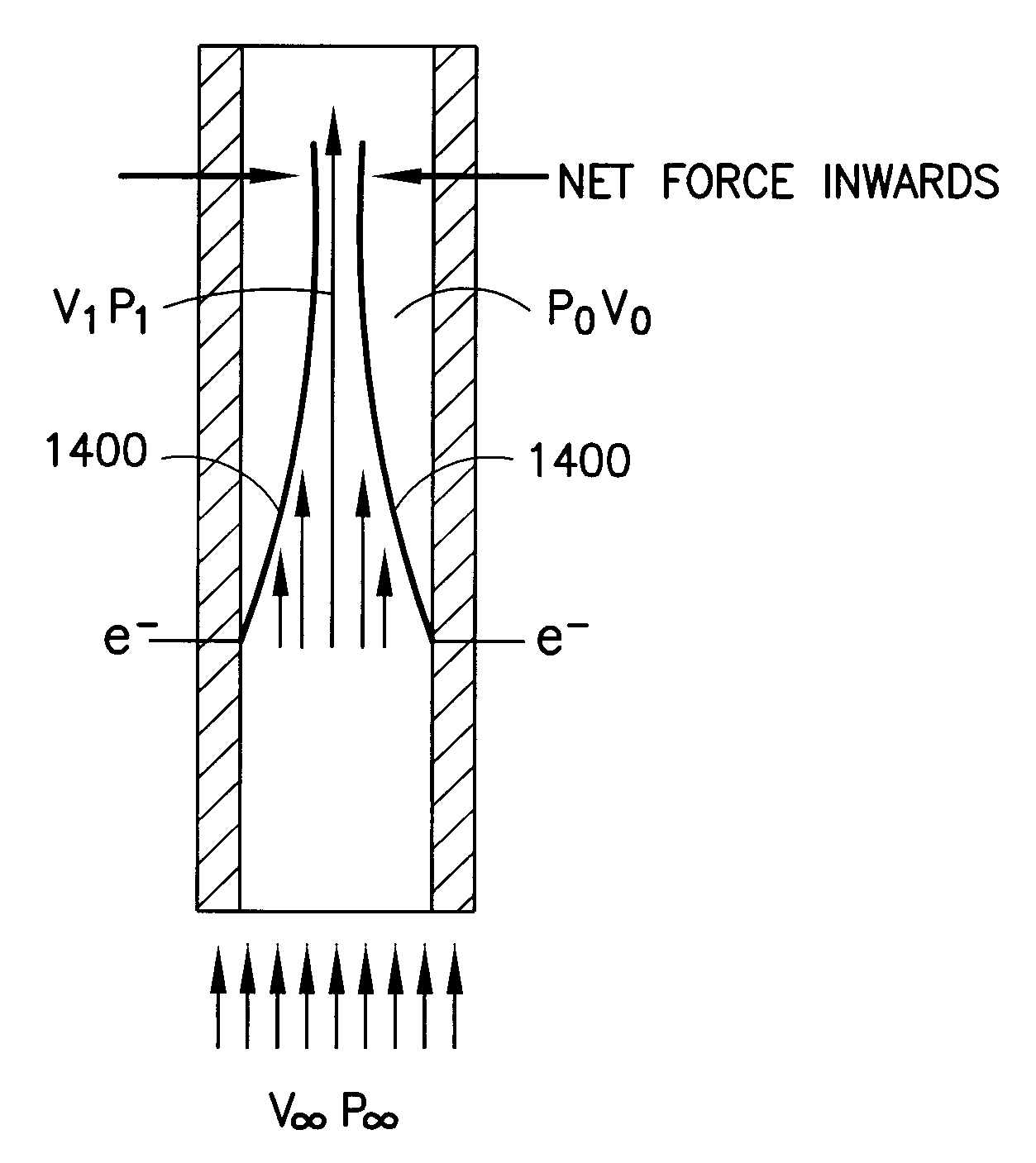
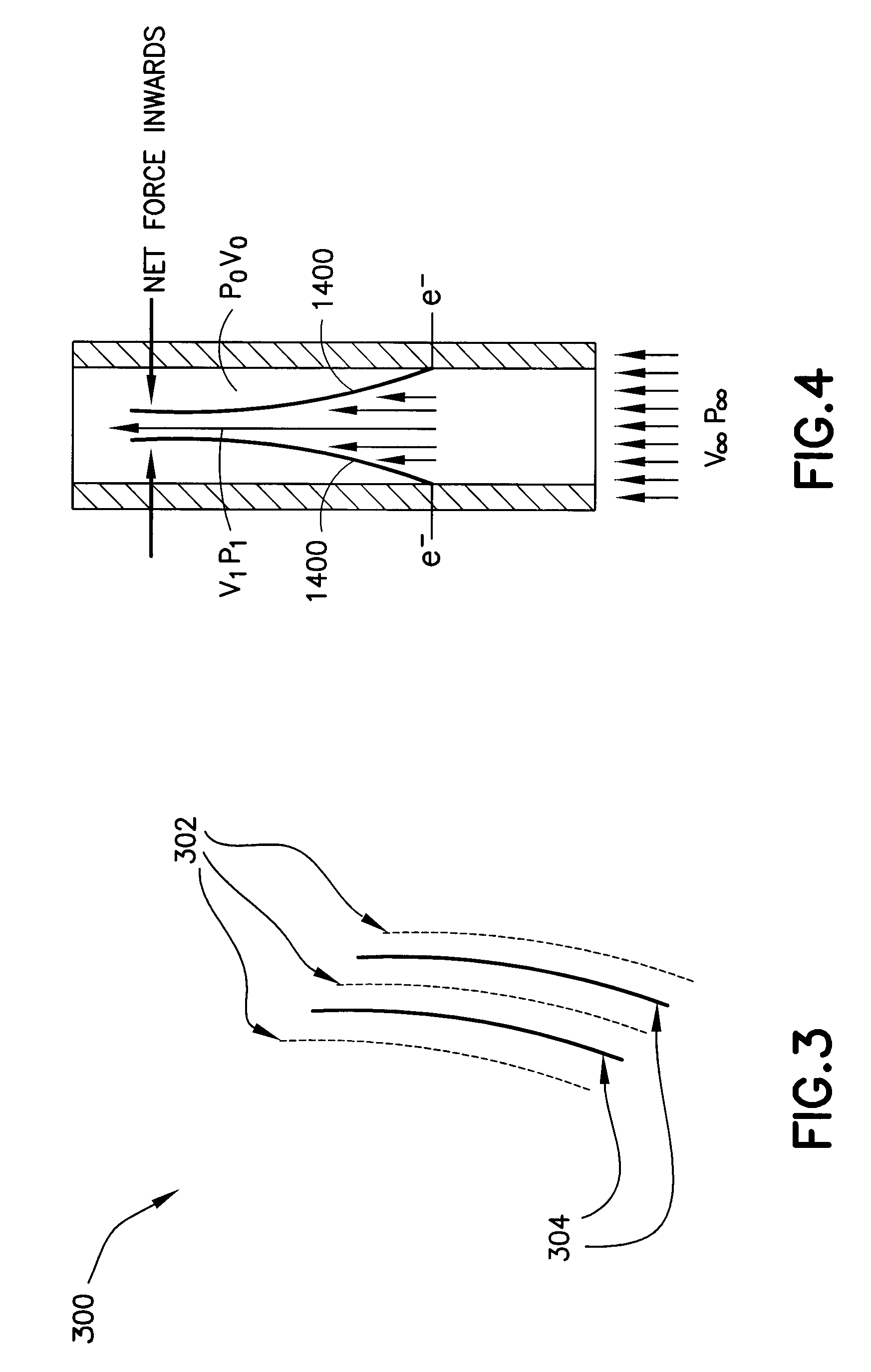
Electrical energy is produced at a remote or close site by converting kinetic energy from fluid flow with membranes that generates electrical energy in response to deformation by the fluid flow passing though a piezo electric medium attached to the deforming membranes. Sets of membranes define variable fluid flow restrictors that oscillate due to interaction of the force of fluid flow and Bernoulli Effect. The device can be tuned to different flow regimes in order to enhance energy conversion efficiency. Each membrane may include one or more layers of piezoelectric material separated by insulating / stiffening layers. Further, the device may be mounted in a secondary flow path such as a side package or annular tube.

Description

FIELD OF THE INVENTION[0001]This invention is generally related to harvesting energy, and more particularly to converting kinetic energy from flowing fluid into electrical energy to power equipment in a close or remote locations from the area where the energy is being harvested.BACKGROUND OF THE INVENTION[0002]In order to recover natural resources from subterranean formations it is often necessary to perform tasks related to exploration, monitoring, maintenance and construction in remote locations that are either difficult or impractical for personnel to reach directly. For example, boreholes may be drilled tens of thousands of meters into the earth, and in the case of offshore drilling, the borehole may be thousands of meters under water. One of the technical challenges to performing tasks in such remote locations is providing power to equipment. It is known to power downhole and undersea equipment via either stored energy or wireline connection to the surface. However, both of the...

Claims


Application Information

Patent Timeline
Patent Type & Authority Patents(United States)
IPC IPC(8): H01L41/08H10N30/00H10N30/30
CPCE21B41/0085H02N2/185Y10S310/80
Inventor CHEN, KUO CHIANGPABON, JAHIR A.GANGULY, PARTHAOCALAN, MURATGUERRERO, JULIO C.FORBES, KEVIN J.
Owner SCHLUMBERGER TECH CORP
Learn More