Seal usable between thermally movable components

a technology of moving components and sealing, which is applied in the direction of machines/engines, liquid fuel engines, light and heating apparatus, etc., can solve the problems of conventional sealing, affecting engine performance, and reducing engine performance, so as to reduce leakage, reduce gap, and increase engine efficiency

Inactive Publication Date: 2009-07-21
SIEMENS ENERGY INC
View PDF31 Cites 22 Cited by
  • Summary
  • Abstract
  • Description
  • Claims
  • Application Information

AI Technical Summary

Benefits of technology

[0007]The seal may be used to seal adjacent thermally movable components. For instance, the seal may be inserted into adjacent cavities in thermally movable components. The seal may be sized such that a relatively small gap, if any, exists between the walls of the cavity in the thermally movable components and the first and second ends of the seal. At base load of a turbine engine, a seal of this configuration substantially limits leakage of fluids past the seal. In at least one embodiment, the seal may limit cooling fluids from mixing with hot gases. As the turbine engine approaches design load, the seal and the thermally movable components are heated, and the compliant material contacts the thermally movable components, wherein the thermally compliant material may deform. In at least one embodiment in which the complaint material is formed from teeth, the teeth flex when placed in contact with the thermally movable components. When cooled, the teeth return to their original shape.
[0008]An advantage of this invention is that the compliant region of the seal enables the seal to be sized closely to the size of the opening between adjacent thermally movable components, thereby reducing the gap between the seal and the components at transient operating conditions. Such a configuration enables the seal to realize a reduction in leakage past the seal by as much as 25% over conventional seals, which increases the efficiency of the engine.

Problems solved by technology

As a result, turbine engines often contain secondary flow paths forming cooling systems for prolonging the life of turbine components and reducing the likelihood of failure as a result of excessive temperatures.
Allowing the combustion gases and cooling gases found in secondary flow paths to mix is detrimental to engine performance and is generally undesirable.
Sealing this leakage path is problematic because the seal must be able to accommodate radial, circumferential, and angular movements between the components while maintaining an adequate seal.
Such movements are often caused by assembly misalignment, vibration during operation of a turbine engine, and different thermal expansion between adjacent components.
Conventional seals, as shown in FIG. 1, typically are inefficient at sealing these gaps because many conventional seals are rigid and do not conform to the misalignment.
If clearance is not included in a rigid seal, the seal can bind and cause damage to the seal or adjacent components.
While this clearance is necessary with rigid seals, such clearance increases the leakage around the seal resulting in a decrease in performance.

Method used


Image

  • Seal usable between thermally movable components
  • Seal usable between thermally movable components
  • Seal usable between thermally movable components

Examples


Embodiment Construction

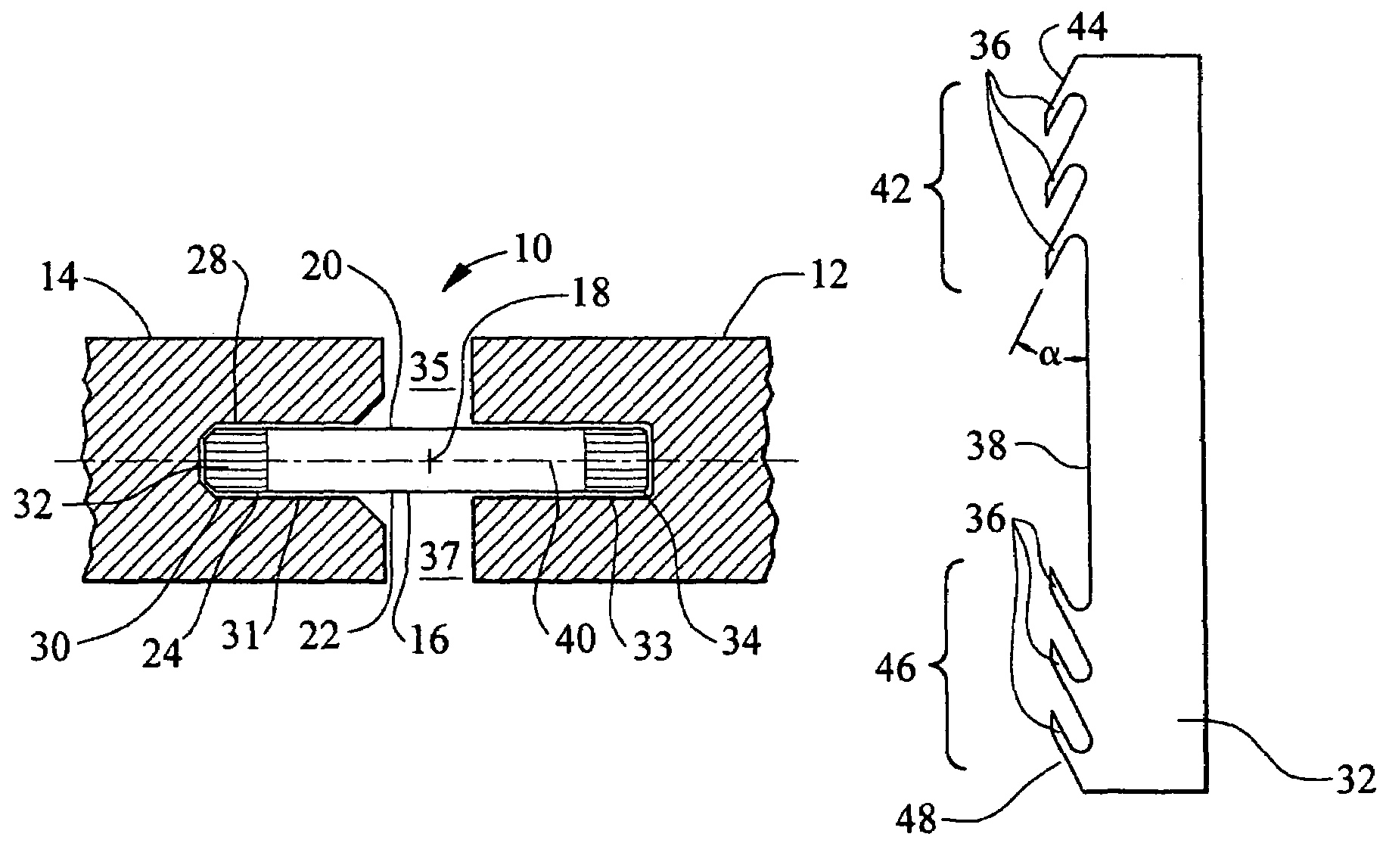
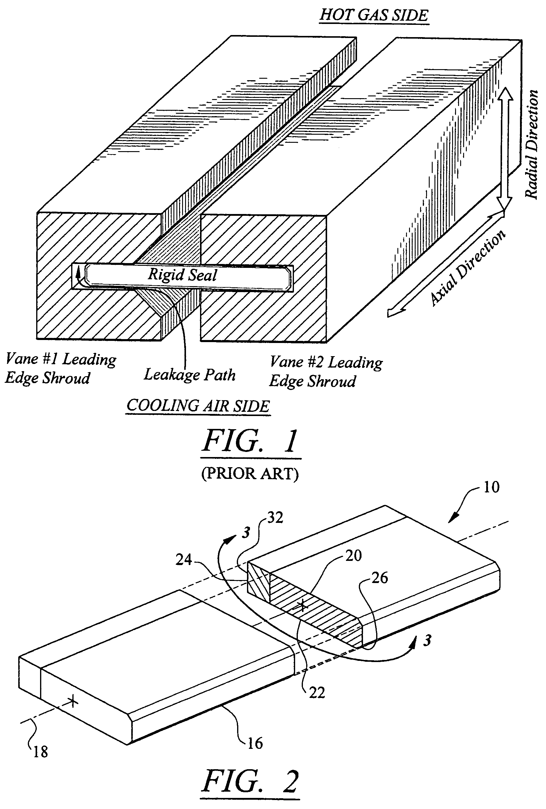
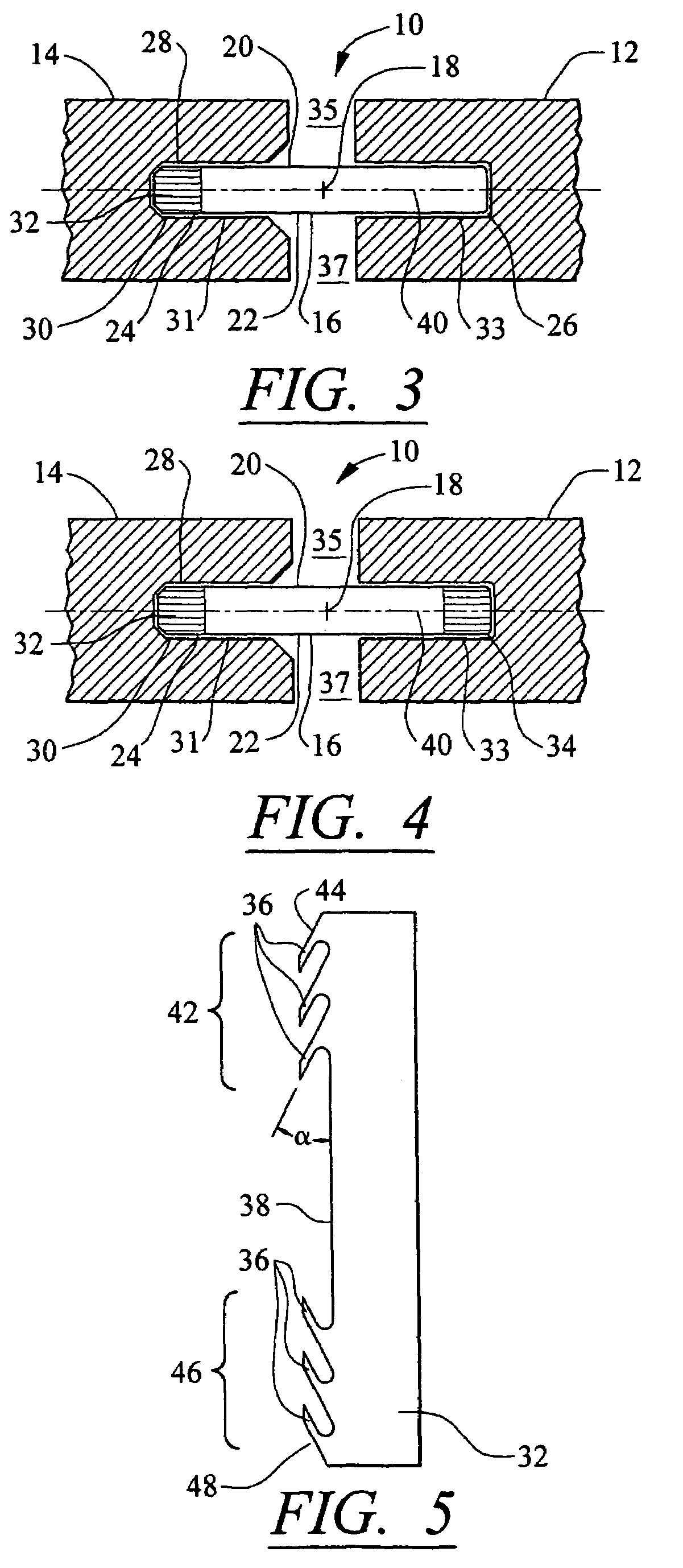
[0021]As shown in FIGS. 2-10, this invention is directed to a seal 10 usable between two thermally movable components 12 and 14. In at least one embodiment, the seal 10 may be used to seal components of a turbine engine. For instance, the seal 10 may be used to seal components of a turbine engine in which the thermally movable components 12 and 14 may be, but are not limited to, leading edge shrouds, isolation rings, ring segments, and vane segments. In a turbine engine, the seal 10 may be used to prevent cooling air from mixing with combustion gases. In addition, as shown in FIGS. 2 and 3, the seal 10 may be formed from a body 16 having a longitudinal axis 18 and be configured for sealing space between adjacent components to prevent fluid from passing between adjacent components 12 and 14. The body 16 may be formed from rigid materials capable of withstanding the environment in which it is placed, which may include hot combustion gases. In at least one embodiment, the longitudinal ...


PUM


Abstract

A seal usable between two thermally movable components to prevent fluids from mixing. For instance, the seal may be used to seal thermally movable components of a turbine engine that may include, but are not limited to, leading edge shrouds, isolation rings, ring segments, and vane segments. The seal may be formed from a body having a cross-section generally orthogonal to a longitudinal axis and include a first side, a second side generally opposite to the first side, a first end, and a second end generally opposite to the first end. A compliant material may be coupled to the first or second end, or both, and may absorb thermal expansion of the two thermally movable components. The seal may reduce leakage flow paths between the seal and the thermally movable components.

Description

FIELD OF THE INVENTION[0001]This invention is directed generally to seals, and more particularly to seals usable between thermally movably components such as those commonly found in turbine engines.BACKGROUND[0002]Typically, gas turbine engines include a compressor for compressing air, a combustor for mixing the compressed air with fuel and igniting the mixture, and a turbine assembly for producing power. Combustors often operate at high temperatures that may exceed 2,500 degrees Fahrenheit. As a result, turbine engines often contain secondary flow paths forming cooling systems for prolonging the life of turbine components and reducing the likelihood of failure as a result of excessive temperatures. Allowing the combustion gases and cooling gases found in secondary flow paths to mix is detrimental to engine performance and is generally undesirable.[0003]Many turbine engines include noteworthy leakage paths between gas turbine components, such as adjacent vanes, ring segments, et cet...

Claims


Application Information

Patent Timeline
Patent Type & Authority Patents(United States)
IPC IPC(8): F16J15/02F01D25/26F01D5/20F16J15/32
CPCF16J15/3288F16J15/322
Inventor PAPROTNA, HUBERTUS EDWARDLITTLE, DAVID A.
Owner SIEMENS ENERGY INC
Why Eureka
Try Eureka