Transformer

a transformer and transformer technology, applied in the field of transformers, can solve the problems of time-consuming and laborious procedure of sheathing the tube b>14/b>, failure to stably control the leakage inductance of the transformer b>1/b>, and increase the winding space , the effect of enhancing the efficiency of electric conversion

Active Publication Date: 2011-11-08
DELTA ELECTRONICS INC
View PDF19 Cites 22 Cited by
  • Summary
  • Abstract
  • Description
  • Claims
  • Application Information

AI Technical Summary

Benefits of technology

[0008]Another object of the present invention provides a transformer having an air gap disposed over the primary winding coil, thereby stably controlling the leakage inductance.
[0009]A further object of the present invention provides a transformer having increased winding space, enhanced electric conversion efficiency, and reduced heat generation.

Problems solved by technology

Under this circumstance, the leakage inductance of the transformer 1 fails to be stably controlled.
For example, the tube 14 may be thermally damaged.
The procedure of sheathing the tube 14 is time-consuming and labor-intensive.
In addition, the use of the tube 14 increases the cost of the transformer.

Method used


Image

  • Transformer
  • Transformer
  • Transformer

Examples


first embodiment

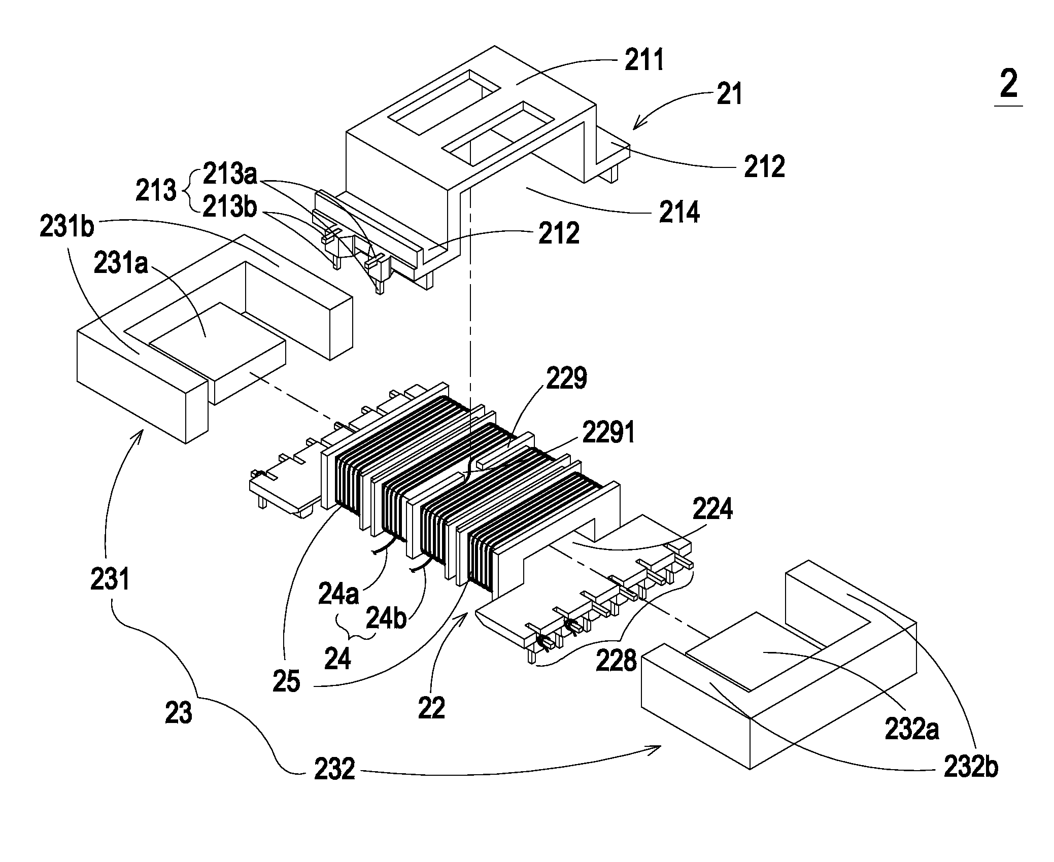
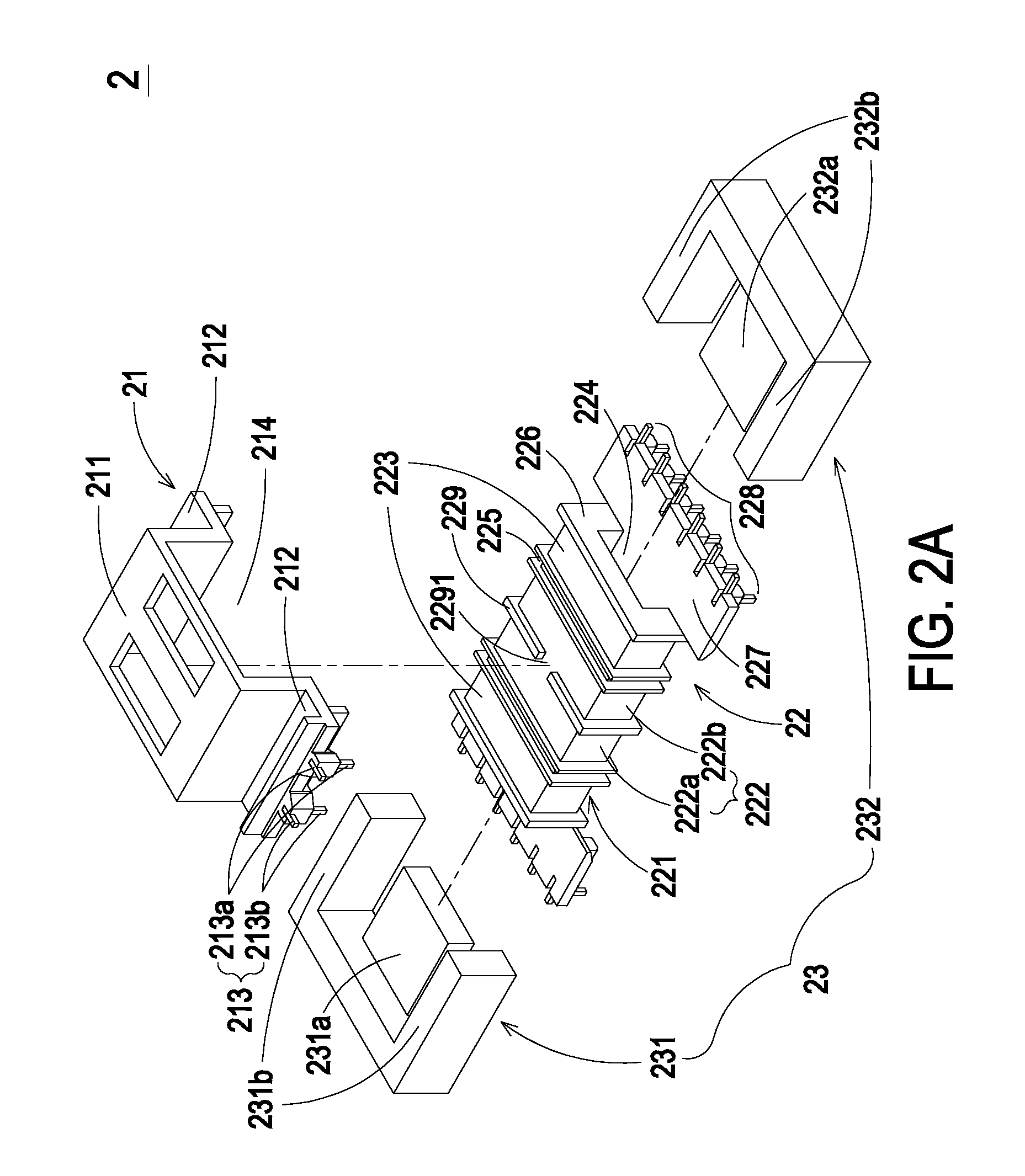
[0019]FIG. 2A is a schematic exploded view illustrating a transformer according to the present invention, in which the winding coils are not shown. As shown in FIG. 2A, the transformer 2 comprises a covering member 21, a bobbin 22, a magnetic core assembly 23, a primary winding coil 24, and plural secondary winding coils 25 (see FIG. 2B). The covering member 21 is combined with the bobbin 22. The covering member 21 comprises a covering member body 211, a recess 212 and plurality pins 213. In this embodiment, the plural pins 213 comprise a first pin 213a and a second pin 213b. The covering member body 211 comprises a receptacle 214. The recess 212 is disposed beside the covering member body 211. The pins 213 are disposed outside the recess 212. The bobbin 22 comprises a bobbin body 221, a channel 224, plural partition plates 225, two side plates 226, and two connecting bases 227. The channel 224 runs through the bobbin body 221. In this embodiment, the bobbin body 221 is substantiall...

second embodiment

[0021]In the embodiment of FIG. 2A, the transformer 2 has two single-trough second winding sections 223. It is noted that the number of the single-trough second winding sections 223 could be varied as required. FIG. 3 is a schematic exploded view illustrating a transformer according to the present invention. As shown in FIG. 3, one first winding section 222 and four single-trough second winding sections 312 are defined on the surface of the bobbin body 311 of the bobbin 31 by four partition plates 225 and the side plates 226. The four single-trough second winding sections 312 include the second winding sections 312a, 312b, 312c and 312d. Correspondingly, four secondary winding coils (not shown) are respectively wound around the four single-trough second winding sections.

[0022]Please refer to FIG. 2A again. The magnetic core assembly 23 comprises a first magnetic part 231 and a second magnetic part 232. The first magnetic part 231 of the magnetic core assembly 23 comprises a middle p...


PUM

PropertyMeasurementUnit
magneticaaaaaaaaaa
voltagesaaaaaaaaaa
leakage inductanceaaaaaaaaaa

Abstract

A transformer includes a covering member, a bobbin, a primary winding coil, plural secondary winding coils, and a magnetic core assembly. The covering member includes plural pins. The bobbin is combined with the covering member, and includes a bobbin body and a channel. A first winding section and plural single-trough second winding sections are defined on the bobbin body. The single-trough second winding sections are arranged at bilateral sides of the first winding section. The channel runs through the bobbin body. The primary winding coil is wound around the first winding section of the bobbin, and connected with the pins. The secondary winding coils are wound around respective single-trough second winding sections of the bobbin. The magnetic core assembly is partially embedded into the channel of the bobbin.

Description

FIELD OF THE INVENTION[0001]The present invention relates to a transformer, and more particularly to a transformer having plural single-trough second winding sections.BACKGROUND OF THE INVENTION[0002]A transformer has become an essential electronic component for voltage regulation into required voltages for various kinds of electric appliances.[0003]Since the leakage inductance of the transformer has an influence on the electric conversion efficiency of a power converter, it is very important to control leakage inductance. In the power supply system of the new-generation electric products such as LCD televisions, leakage inductance transformers (e.g. LLC transformers) become more and more prevailing. Generally, the current generated from the power supply system will pass through a LC resonant circuit composed of an inductor L and a capacitor C, wherein the inductor L is inherent in the primary winding coil of the transformer. At the same time, the current with a near half-sine wavef...

Claims


Application Information

Patent Timeline
Patent Type & Authority Patents(United States)
IPC IPC(8): H01F27/29
CPCH01F27/29H01F27/325H01F38/08H01F3/14H01F27/06
Inventor TSENG, HSIANG-YITSAI, HSIN-WEI
Owner DELTA ELECTRONICS INC
Why Eureka
Try Eureka