

High-pressure pump
a high-pressure pump and pump body technology, applied in the direction of machines/engines, liquid fuel engines, positive-displacement liquid engines, etc., can solve the problems of cylinder deformation, cylinder deformation gradually increasing frictional heat, and cylinder seizur
- Summary
- Abstract
- Description
- Claims
- Application Information
AI Technical Summary
Benefits of technology
Problems solved by technology
Method used
Image

Examples
first embodiment
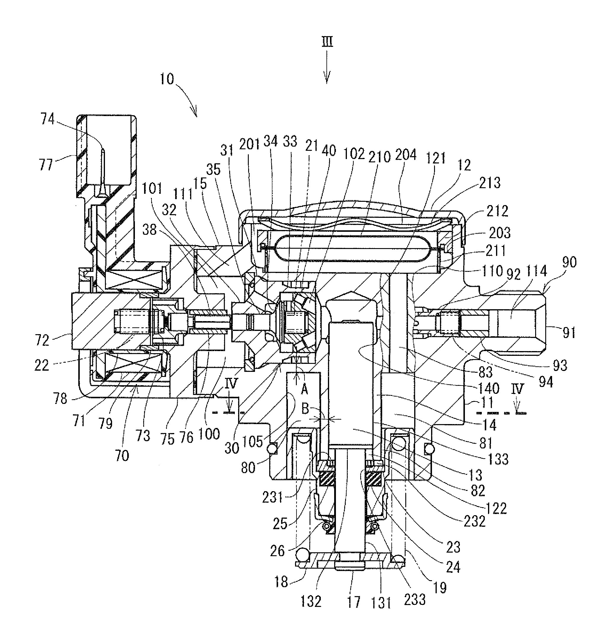
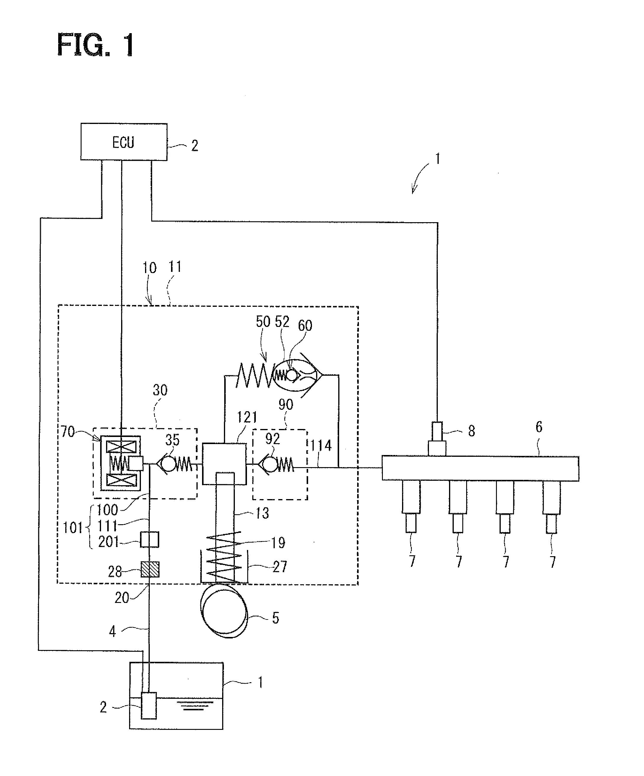
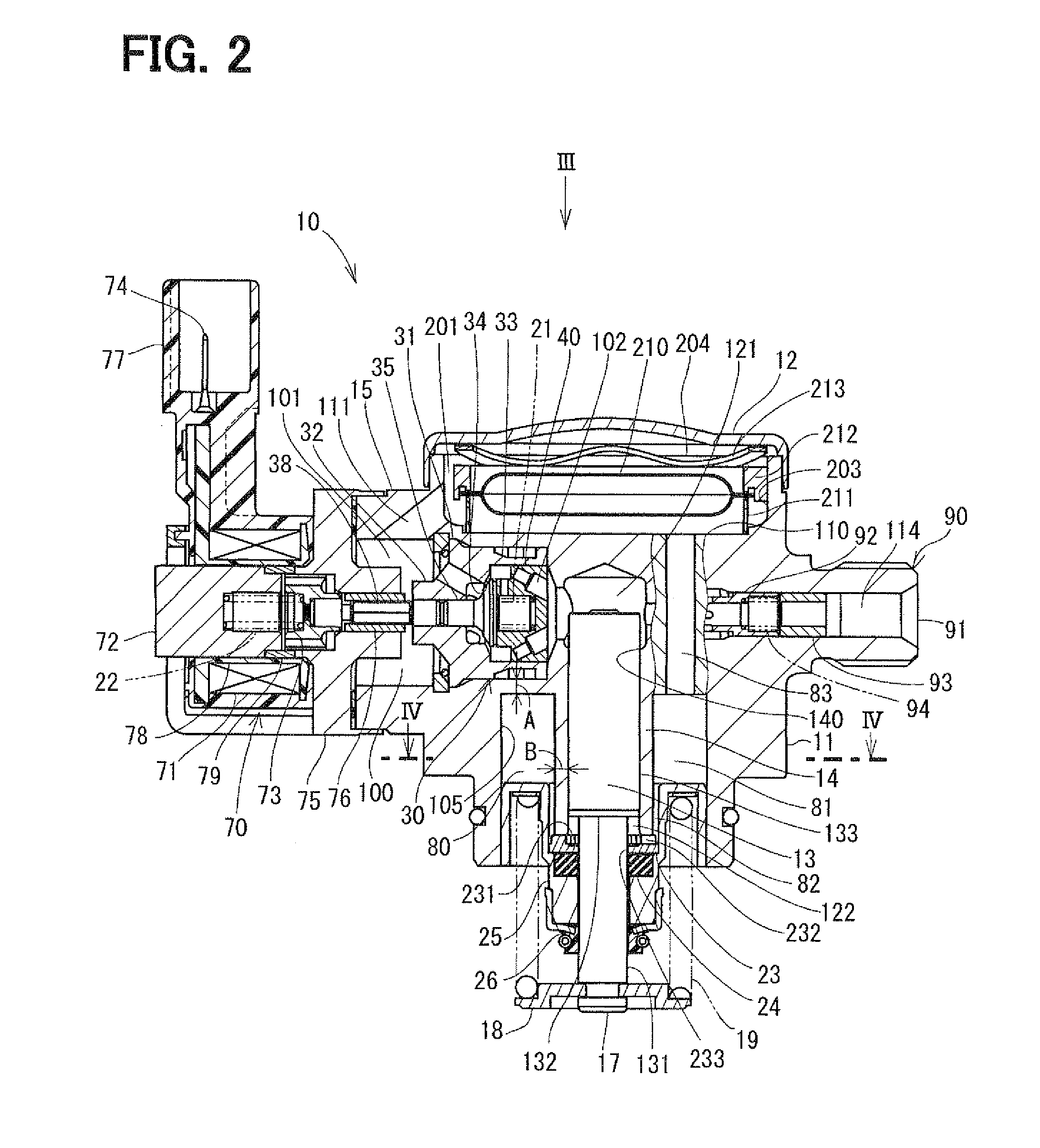
[0031]FIG. 1 is a schematic view showing a fuel supply system including a high-pressure pump according to a first embodiment.
[0032]A portion encompassed by a dashed line represents a pump body 11 of a high-pressure pump 10. Fuel in a fuel tank 1 is pumped up by a low-pressure pump 3 according to a command signal from an electronic control unit (ECU) 2. The fuel is introduced to a fuel inlet 20 of a high-pressure pump 10 through a low-pressure fuel pipe 4.
[0033]The fuel passed through the fuel inlet 20 flows into a supply passage 100 of a suction valve 30 through a filter 28, a damper chamber 201 and an introduction passage 111. The filter 28 removes foreign matters contained in the fuel. The damper chamber 201 attenuates pressure pulsation. In the present embodiment, a passage including a fuel passage between the fuel inlet 20 and the damper chamber 201, the damper chamber 201, the introduction passage 111, and the supply passage 100 is referred to as a low-pressure fuel passage 101...
second embodiment
[0084]Referring to FIG. 6, a second embodiment of the invention will be described. In each of following embodiments, the substantially same parts and the components as those in the first embodiment are indicated with the same reference numeral and the same description will not be reiterated.
[0085]In the second embodiment, the cylindrical space 84 is shaped tapered. The cylinder 14 has a tapered portion 141 and a cylindrical portion 142. A wall thickness “C” of the cylinder 14 is thicker than a wall thickness “D” of the cylinder 14.
[0086]A fuel film is formed in a clearance between the cylinder 14 and the plunger 13. In this clearance, the fuel pressure decreases along a direction from the pressurization chamber 121 to the variable volume chamber 122 according to Hagen-Poiseuille equation. Corresponding to the variation in fuel pressure, the cylinder 14 has a tapered portion 141 so that a deformation of the cylinder 14 is restricted. Thereby, frictional heat is restricted between the...
third embodiment
[0087]Referring to FIG. 7, a third embodiment of the invention will be described. A plurality of communication passages 83 hydraulically connecting the cylindrical space 80 and the damper chamber 201 are formed. These communication passages 83 extend axially in parallel with the cylinder 14. Each of communication passages 83 has an opening 831 which opens to the cylindrical space 80.
[0088]While the plunger 13 reciprocates and the volume of the variable volume chamber 122 is varied, the fuel circulates between the variable volume chamber 122 and the cylindrical space 80. The fuel circulates between the cylindrical space 80 and the damper chamber 201 through the openings 831 and communication passages 83. The fuel of low temperature is supplied from the fuel tank 1 to the damper chamber 201. Thus, the variable volume chamber 122 and the cylindrical space 80 are filled with the fuel of low temperature.
[0089]The communication passages 83 improve the circulation of the fuel between the c...
PUM
 Abstract
Description
Claims
Application Information