Self-monitoring system for evaluating and controlling adjustment requirements of leakage restricting devices in rotodynamic pumps

a leakage restricting device and self-monitoring system technology, applied in the field of rotodynamic pumps, can solve the problems of dramatic increase in wear, and reducing the service life of restriction configurations, so as to reduce wear and increase pump performance.

Active Publication Date: 2009-07-16
WEIR SLURRY GRP INC
View PDF15 Cites 23 Cited by
  • Summary
  • Abstract
  • Description
  • Claims
  • Application Information

AI Technical Summary

Benefits of technology

[0014]In accordance with the present invention, an automatic adjustment system is provided for effecting adjustment of the leakage restricting mechanism between the rotating and non-rotating elements of the pump to restrict leakage and to establish desired gap dimensions between the rotating and non-rotating elements of a pump. The automatic adjustment system is structured to be self-monitoring for determination of when an adjustment of the leakage restricting mechanism is warranted by the conditions of the pump, and is structured with adjusting mechanisms that may be self-adjusting responsive to the monitored conditions of the pump. The automatic adjustment system is described herein with respect to use in a centrifugal pump of the slurry type primarily to reduce wear, but may be adapted for use in any rotodynamic pump with a resulting increase in pump performance.

Problems solved by technology

Such fluid recirculation, typically characterized as leakage, results in a consequential loss of pump performance and a dramatic increase in wear when there is a presence of solid particles in the fluid.
These restriction configurations may suffer from declining performance in service if an adjustment means is not present to compensate for wear.
Uncontrolled or unmonitored clearances between the components allow leakage, which accelerates wear.
As a result, such arrangements may still be vulnerable to over adjustment and / or lack of sufficient adjustment, which may lead to undesirable fluid recirculation, or leakage, and wear between rotating and stationary elements of the pump.
Moreover, flush water is not always available or practical for a given application.
Further, the relative position of the sealing elements or leakage restricting mechanisms may not be accurately controlled by manual adjustment means due to variables of the application.

Method used


Image

  • Self-monitoring system for evaluating and controlling adjustment requirements of leakage restricting devices in rotodynamic pumps
  • Self-monitoring system for evaluating and controlling adjustment requirements of leakage restricting devices in rotodynamic pumps
  • Self-monitoring system for evaluating and controlling adjustment requirements of leakage restricting devices in rotodynamic pumps

Examples


Embodiment Construction

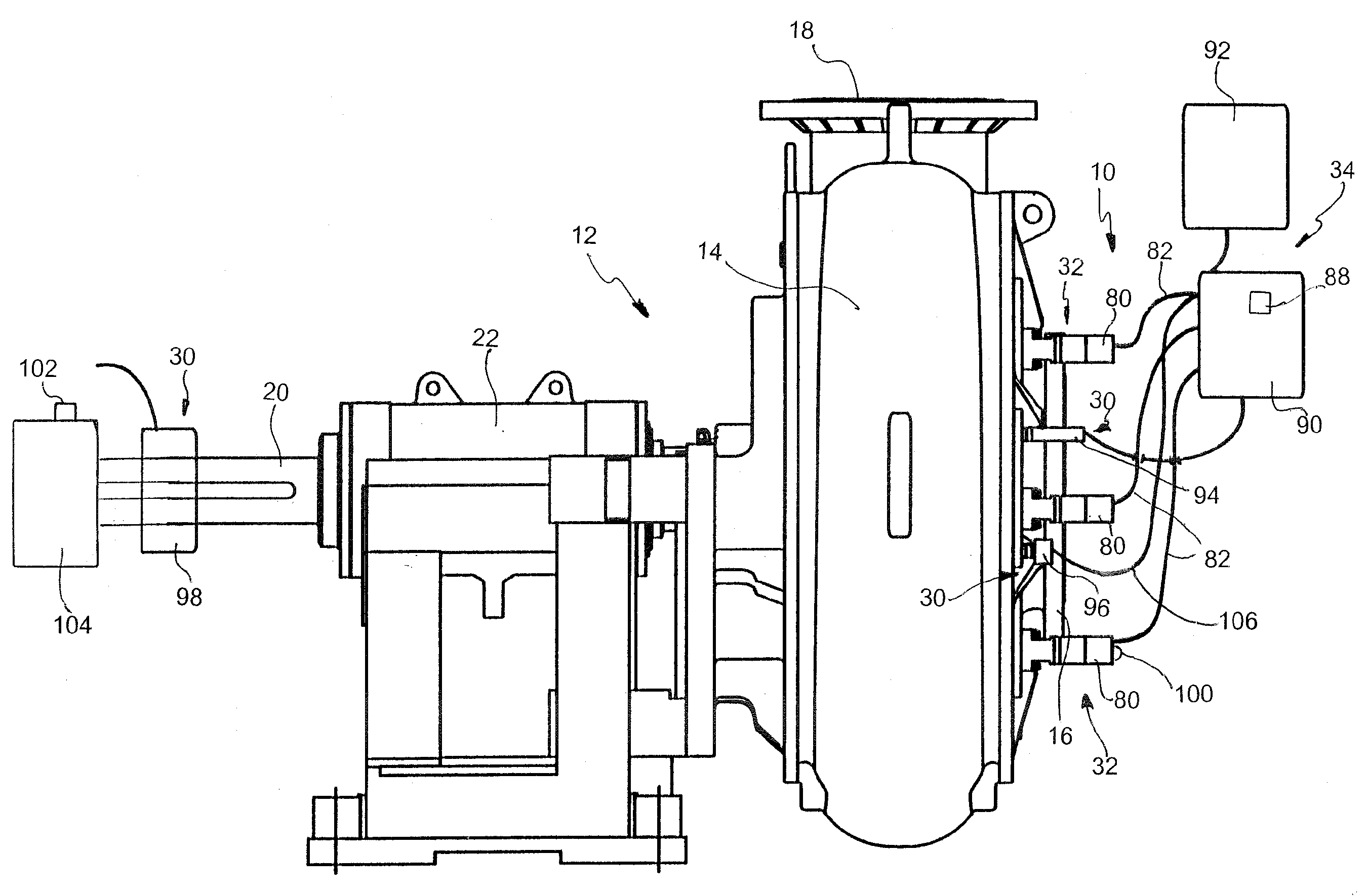
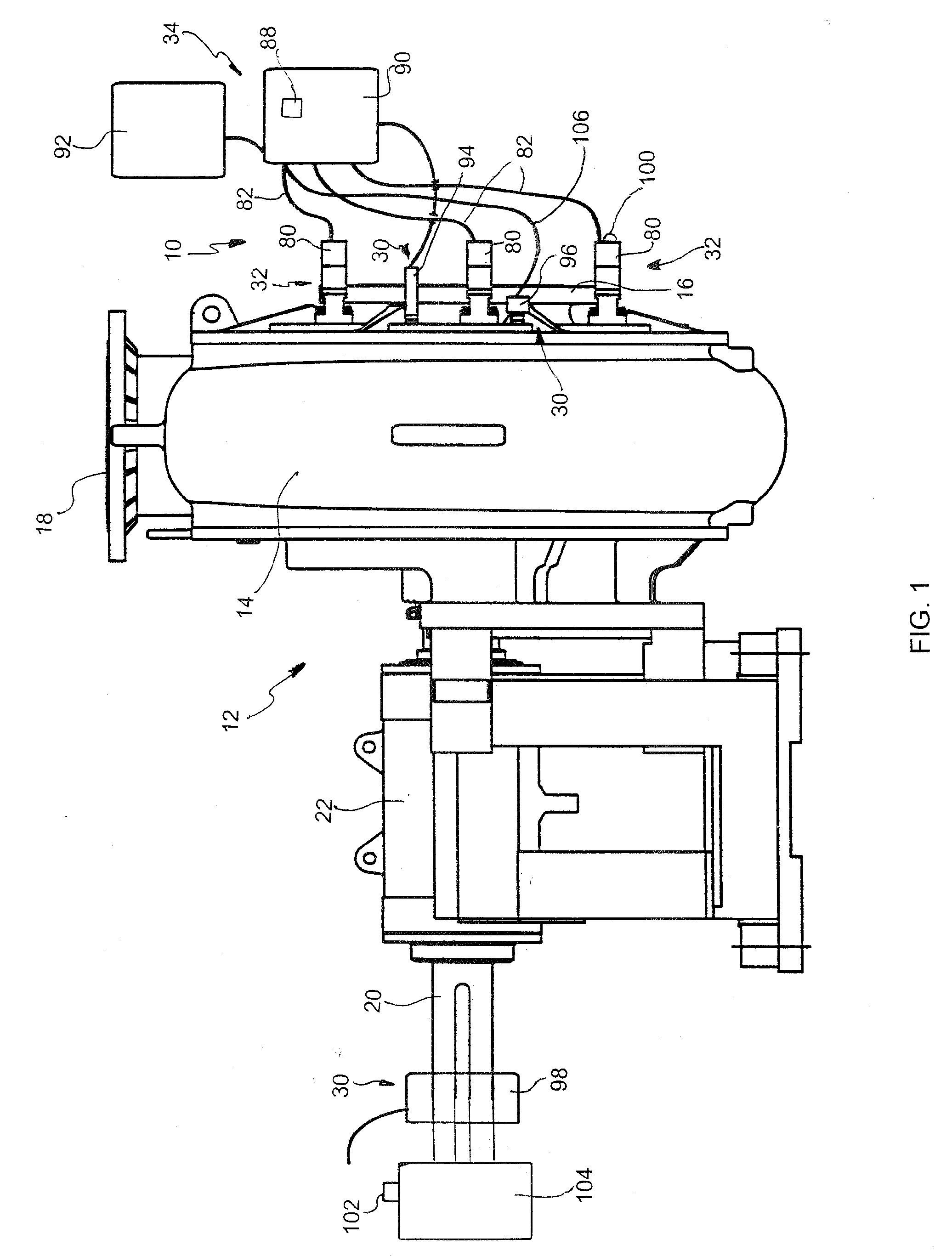
[0036]In the drawings, where the same or similar elements are indicated by the same reference numerals, FIG. 1 illustrates an automatic adjustment system 10 encompassed by the present invention installed in a rotodynamic pump 12. The rotodynamic pump 12 generally comprises a pump casing 14 having a fluid inlet 16 and a fluid outlet 18 for discharge. The pump 12 further includes a drive mechanism 20 for driving the rotating elements of the pump, and the drive mechanism 20 is positioned through a bearing assembly 22 to which the pump casing 14 is secured in known manner.

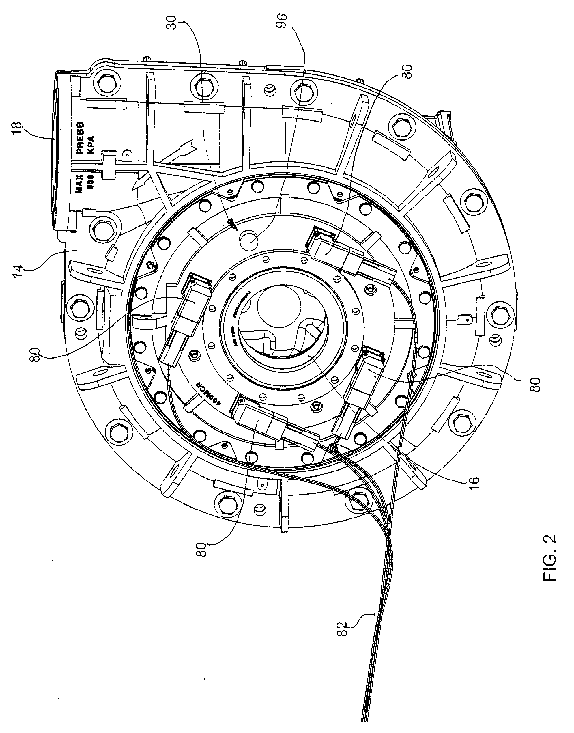
[0037]The automatic adjustment system 10 of the present invention is generally comprised of at least one sensor or detection mechanism 30 (of which a plurality of various sensor or detection mechanisms are shown for illustrative purposes), at least one adjustment device 32 and a control system 34. The present invention may preferably comprise a plurality of adjustment devices 32 which, as shown more clearly in FIG. 2, ...


PUM


Abstract

A self-monitoring adjustment system is provided for evaluating and effecting adjustment of the leakage restricting mechanism between the rotating and non-rotating elements of a rotodynamic pump to restrict leakage and to establish desired gap dimensions between the rotating and non-rotating elements of the pump. The adjustment system is structured to be self-monitoring for determination of when an adjustment of the leakage restricting mechanism is warranted by the conditions of the pump, and is structured with adjusting mechanisms that are self-adjusting responsive to the monitored conditions of the pump, though manual adjustment is also enabled.

Description

BACKGROUND OF THE INVENTION[0001]1. Field of the Invention[0002]This invention relates to rotodynamic pumps, and specifically relates to means for controlling and automating the adjustment devices for restricting fluid recirculation and reducing wear between rotating and non-rotating fluid processing elements of rotodynamic pumps, especially those pumps that are suitable for handling slurries and those pumps that are, or can be, configured with adjustable wear components designed as leakage restricting devices.[0003]2. Description of Related Art[0004]Rotodynamic pumps, such as centrifugal pumps, are commonly known and used for pumping fluids in many types of industries and for many applications. Such pumps generally comprise an impeller (rotating element) housed within a pump casing (non-rotating element) having a fluid inlet and fluid outlet, or discharge. The impeller is typically driven by a motor external to the casing. The impeller is positioned within the casing so that fluid ...

Claims


Application Information

Patent Timeline
Patent Type & Authority Applications(United States)
IPC IPC(8): F01D5/08F01D25/16
CPCF04D27/00F04D29/167F04D29/622
Inventor BOURGEOIS, RONALD J.KOSMICKI, RANDY J.VIAN, JEFFREY C.ERLANDSON, TYLER M.VIKEN, MICHAEL L.
Owner WEIR SLURRY GRP INC
Why Eureka
Try Eureka