Floating brush seal assembly

a technology of floating brush and seal assembly, which is applied in the direction of engine seals, gas turbine plants, machines/engines, etc., can solve the problems of reducing the leakage rate of the seal, the rigid teeth of the labyrinth seal cannot accommodate a “zero clearance” condition without incurring permanent wear or damage to the teeth, and the seal cannot be sealed with a “zero clearance” condition

Inactive Publication Date: 2006-08-22
RTX CORP
View PDF19 Cites 24 Cited by
  • Summary
  • Abstract
  • Description
  • Claims
  • Application Information

AI Technical Summary

Benefits of technology

[0005]It is a further object of the present invention to use a brush seal to control leakage between adjacent components that exhibit high axial and radial growth transients during operation.
[0006]It is a further object of the present invention to provide a seal that can accommodate tight “zero clearance” conditions without permanent wear or damage.
[0007]It is a further object of the present invention to provide a compliant seal that can accommodate a wide range of clearances.
[0008]It is a further object of the present invention to provide a seal that maintains a relatively constant leakage flow rate even as the clearance between the components increases.
[0009]These and other objects of the present invention are achieved in one aspect by a brush seal assembly for sealing a gap between a first component and a second component. The assembly comprises: a body; bristles extending from the body; and an extension from the body, the extension having an elongated slot therein. The slot, when the brush seal assembly mounts between the first and second components, allows the brush seal assembly to float within the gap.

Problems solved by technology

However, labyrinth seals have several drawbacks.
First, the rigid teeth of the labyrinth seal cannot accommodate a “zero clearance” condition without incurring permanent wear or damage to the teeth.
This wear increases the leakage rate of the seal.
Second, the leakage rate of the labyrinth seals increases with the increased clearance between the teeth and the pad.

Method used


Image

  • Floating brush seal assembly
  • Floating brush seal assembly
  • Floating brush seal assembly

Examples


Embodiment Construction

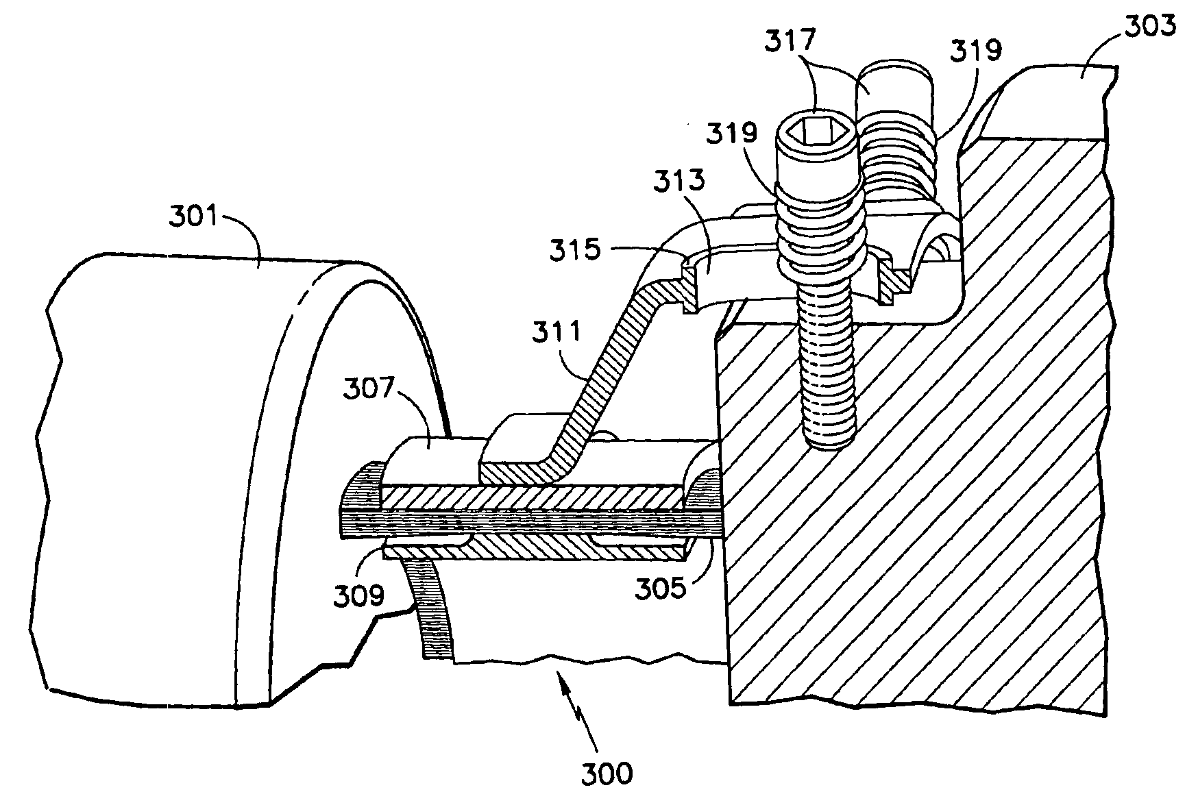
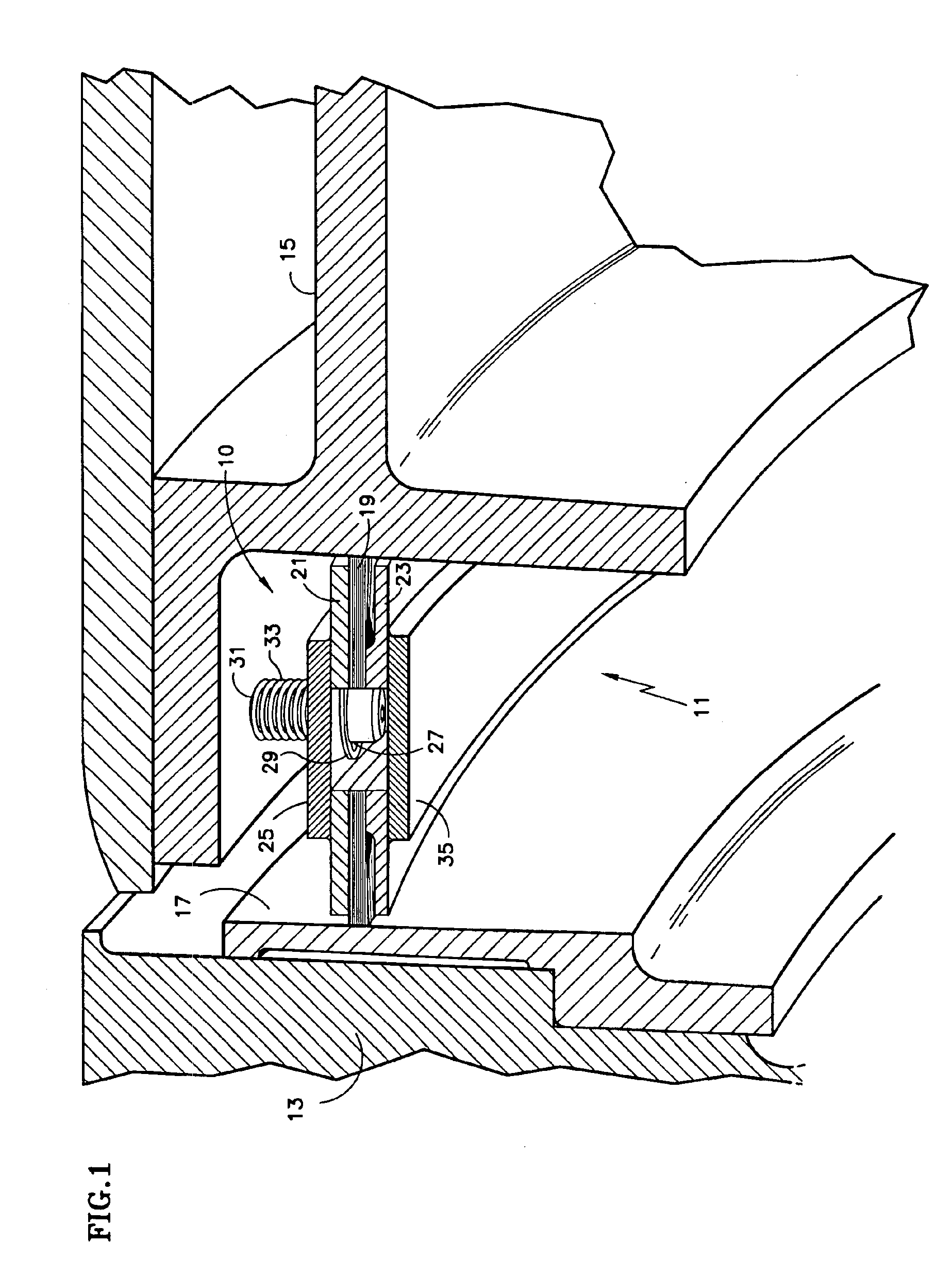
[0018]FIG. 1 displays one alternative embodiment of the present invention. The figure provides a brush seal assembly 10 that inhibits fluid flow through a gap 11 between a first component 13 and a second component 15 of an apparatus such as a gas turbine engine. The components 13, 15 could be stationary or rotating components. The figure shows the first component 13 as a rotating component (such as a turbine disc). The component 13 could include a ring 17 that acts as a land surface for the brush seal assembly 10.

[0019]The figures also show the second component 15 as a stationary component (such as a turbine nozzle). Since the component 15 remains stationary, no need exists for a ring to provide a land surface like the rotating first component 13 may require. As seen in the figures, multiple elements could form the stationary component 15. Alternatively, both components could be stationary components such as adjacent sections of the engine case, compressor stators and the engine cas...


PUM


Abstract

A brush seal assembly for sealing a gap between a first component and a second component, comprising: a body; bristles extending from the body; and an extension from the body, the extension having an elongated slot therein. The slot, when the brush seal assembly mounts between the first and second components, allows the brush seal assembly to float within the gap. An axial brush seal assembly, comprising: a body; bristles extending from the body; and means for allowing movement of the brush seal assembly in an axial direction within the gap. An apparatus, comprising: a first component; a second component spaced from the first component in an axial direction; and an axial brush seal assembly movably mounted between the first and second components. The brush seal assembly can move in said axial direction.

Description

BACKGROUND OF INVENTION[0001]This invention relates to floating brush seal assemblies. Specifically, this invention relates to axial brush seal assemblies that can float in the axial direction within a gap between two components.[0002]Gas turbine engines that exhibit high axial and radial growth transients between adjacent components during operation typically use a labyrinth seal between the components to control leakage. A labyrinth seal comprises a plurality of teeth extending from a disk on one of the components and a honeycomb pad on the other component. The teeth and the pad cooperate to form a serpentine leakage path between the components. The serpentine path inhibits fluid flow between the components.[0003]However, labyrinth seals have several drawbacks. First, the rigid teeth of the labyrinth seal cannot accommodate a “zero clearance” condition without incurring permanent wear or damage to the teeth. This wear increases the leakage rate of the seal. Second, the leakage rat...

Claims


Application Information

Patent Timeline
Patent Type & Authority Patents(United States)
IPC IPC(8): F16J15/44F01D11/00F01D11/12F02C7/28F16J15/22F16J15/32
CPCF01D11/005F16J15/3288F05D2240/56
Inventor ADDIS, MARK E.
Owner RTX CORP
Why Eureka
Try Eureka