Heat exchanger and manufacture method for the same

Inactive Publication Date: 2008-03-06
DENSO CORP
View PDF23 Cites 23 Cited by
  • Summary
  • Abstract
  • Description
  • Claims
  • Application Information

AI Technical Summary

Benefits of technology

[0009]Because the seal member tightly contacts the seal surface due to tackiness, the packing member constructed of the seal member can be restricted of twisting and position-deviating when the core plate and the tank body are fastened to each other. Therefore, the slight gap between the seal surface of the core plate and that of the tank body can be restricted so that the liquid leakage can be reduced.
[0010]According to a second aspect of the present invention, a heat exchanger includes a plurality of tubes in which a fluid flows, a fin which is joined to an outer surface of the tube to improve a heat exchange, a header tank which is arranged at one end of a longitudinal direction of the tube and communicated with the tubes, and a seal member. The header tank includes a core plate and a tank body which define therebetween at least one inner space. The core plate is joined to the tubes. The seal member is arranged betw

Problems solved by technology

Thus, slight gap will occur between the seal surface of the tank body an

Method used


Image

  • Heat exchanger and manufacture method for the same
  • Heat exchanger and manufacture method for the same
  • Heat exchanger and manufacture method for the same

Examples


embodiments

First Embodiment

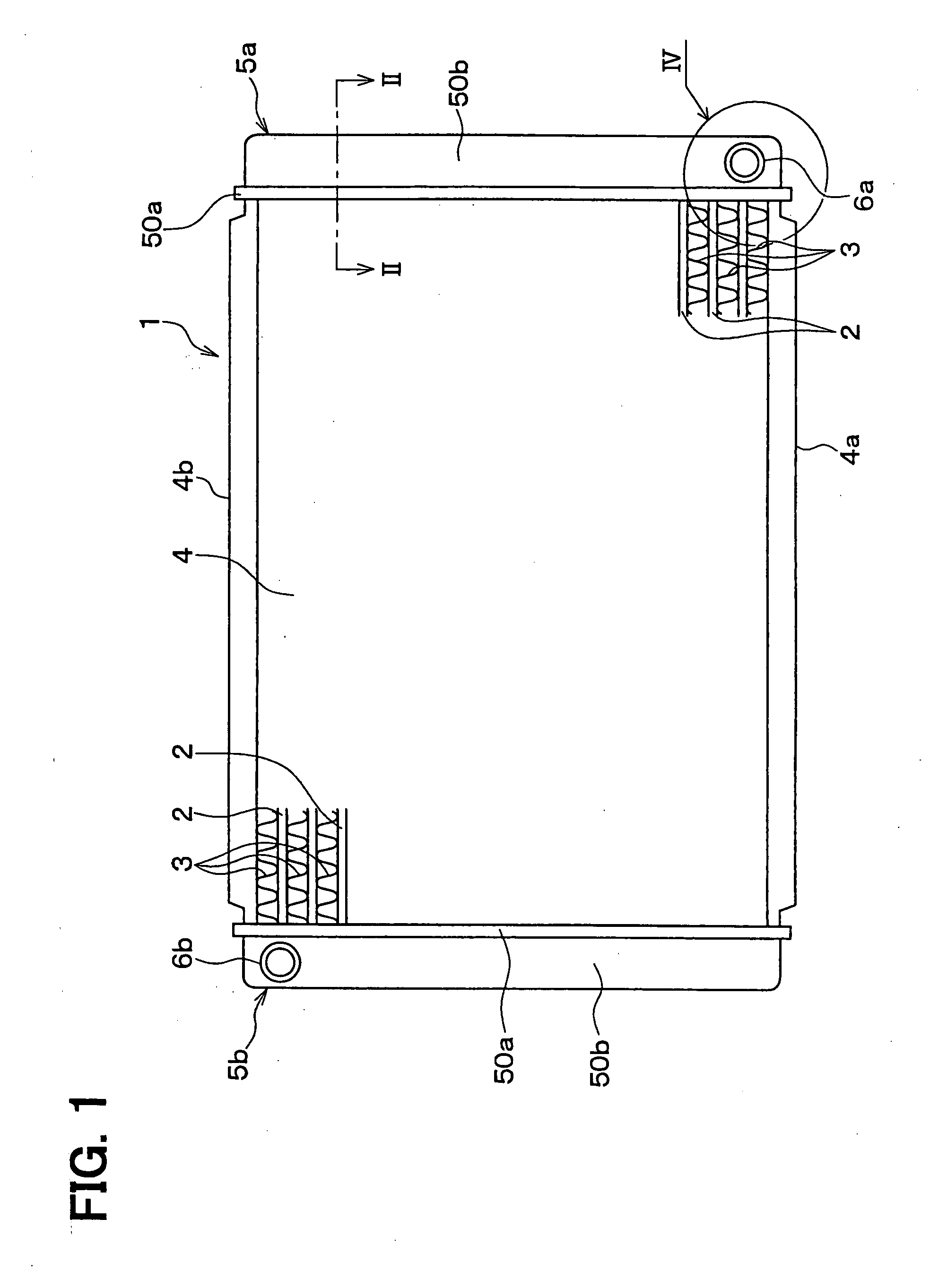
[0034]A heat exchanger according to a first embodiment of the present invention will be described with reference to FIGS. 1-9. The heat exchanger can be suitably used as a radiator 1 of a vehicle, for example. The radiator 1 can be arranged in an engine cabin of the vehicle, to cool fluid (e.g., cooling water) by air blown by a blower.

[0035]As shown in FIG. 1, the radiator 1 is provided with a core unit 4 which includes multiple tubes 2 and multiple fins 3, two side plates 4a, 4b and two header tanks 5a and 5b.

[0036]The tube 2 is constructed of a flat pipe in which cooling water from the engine flows. The tube 2 can be made of a light metal having a high heat conductivity, for example, aluminum. In this embodiment, the tube 2 is constructed of a clad material which surface (facade surface or / and back surface) is covered by a filler material.

[0037]The fin 3 is joined to the outer surface of the tube 2 to increase the area of the heat transferring of the tube 2 with a...

second embodiment

[0078]In the above-described first embodiment, the one tank inner space is formed in the header tank 5a. According to a second embodiment of the present invention, the multiple tank inner spaces (for example, two tank inner spaces) are formed in the header tank 5a.

[0079]As shown in FIG. 10, for example, a partition wall 6c is arranged in the tank body 50b to partition the space in the tank body 50b into the two tank inner spaces 60a and 60b. With reference to FIG. 11, the seal surface 51c having the ring shape and a seal surface 51d corresponding to the partition wall 6c are arranged at the core plate 50a. That is, each of the inner spaces in the header tank 5a is surrounded by the seal member 54.

[0080]In this case, the seal material is applied along the seal surface 51c and the seal surface 51d to respectively surround the inner space 60a and the inner space 60b. As shown in FIG. 12 which is a cross section taken along the line XII-XII in FIG. 11, the bottom of the groove portion ...

third embodiment

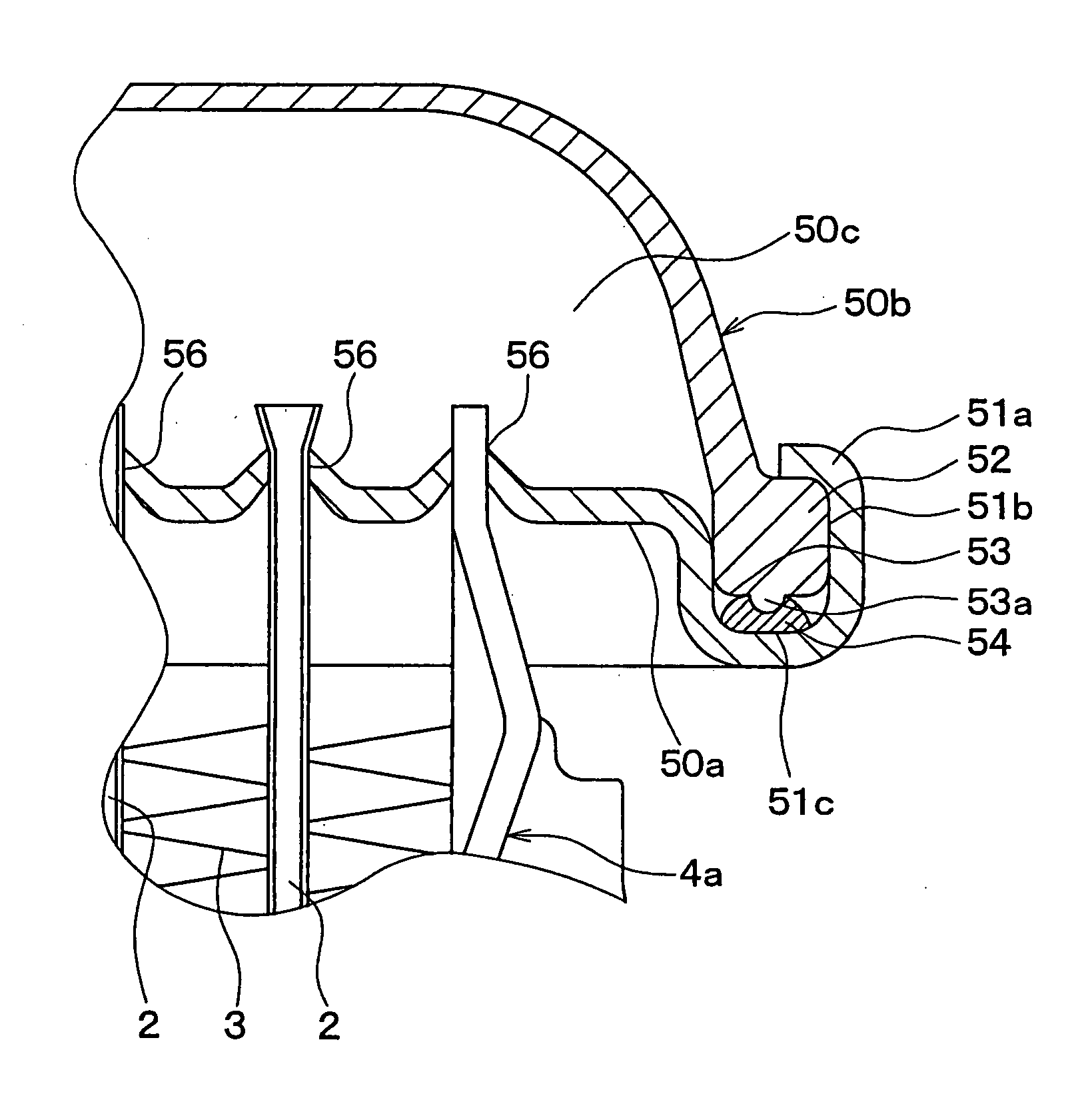
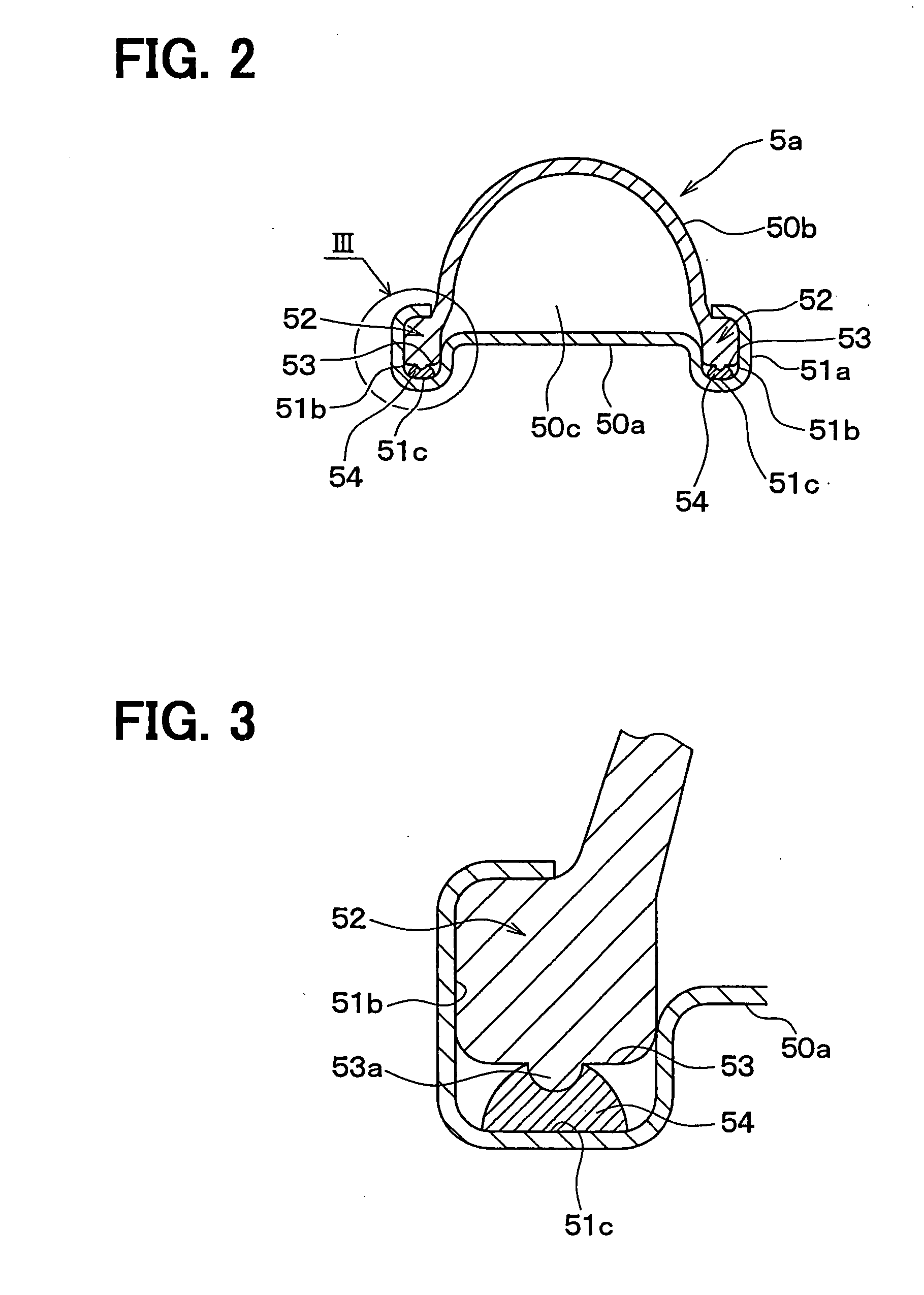
[0085]A third embodiment according to the present invention will be described with reference to FIG. 13. According to this embodiment, a recess 51e is formed at the bottom of the groove portion 51b (having U-like shaped cross section) of the core plate 50a of the header tank 5b, and is positioned within the seal surface 51c of the core plate 50a.

[0086]The recess 51e extends around the periphery of the core plate 50a along the seal surface 51c, to have a ring shape. In this case, the gel seal material or the liquid seal material is applied to fill the recess 51e, and hardened.

[0087]Thus, the seal material is hardened in such a manner that the seal material is engaged in the recess 51e, so that it is difficult for the seal member 54 to leaving the seal surface 51c. Therefore, when the core plate 50a and the tank body 50b are fastened to each other, the position deviation can be further reduced as compared with the first and the second embodiment.


PUM

PropertyMeasurementUnit
Shapeaaaaaaaaaa
Tackinessaaaaaaaaaa

Abstract

A heat exchanger and a manufacture method thereof are provided. Before a tank body and a core plate of a header tank of the heat exchanger are fastened to each other, a gel seal material or a liquid seal material is applied to at least one of a seal surface of the core plate and that of the tank body and hardened. Thus, a seal member which adheres to the seal surface due to the tackiness of the seal member is formed. The core plate and the tank body are fastened to each other in such a state that the part between the seal surface of the core plate and that of the tank body are sealed by the seal member having been hardened. Accordingly, the seal member can be restricted of twisting and position-deviating when the core plate and the tank body are fastened to each other.

Description

CROSS REFERENCE TO RELATED APPLICATION[0001]This application is based on a Japanese Patent Application No. 2006-235022 filed on Aug. 31, 2006, and a Japanese Patent Application No. 2006-235024 filed on Aug. 31, 2006, the disclosures of which are incorporated herein by reference.FIELD OF THE INVENTION[0002]The present invention relates to a heat exchanger and a manufacture method thereof.BACKGROUND OF THE INVENTION[0003]Generally, for example, with reference to JP-3-138116A, a heat exchanger has multiple tubes in which fluid flows, heat-exchanging fins joined to the outer surfaces of the tubes, a first header tank which is communicated with the tubes to shunt the fluid to the multiple tubes, and a second header tank which is communicated with the tubes to collect the fluid from the tubes.[0004]In this case, each of the first header tank and the second tank includes a core plate to which the tubes are joined, a tank body which defines therein a tank inner space together with the core ...

Claims


Application Information

Patent Timeline
IPC IPC(8): F28F9/02B21D53/02
CPCF28F9/0226Y10T29/4935F28F2275/025
Inventor HAKAMATA, OSAMUOZAKI, TATSUONINAGAWA, TOSHIHIDE
Owner DENSO CORP
Why Eureka
Try Eureka