Method and an apparatus for the determination of the 3D coordinates of an object

a technology of 3d coordinates and apparatus, applied in the field of methods for the determination of 3d coordinates of objects, can solve the problems of relative long measuring time, and achieve the effects of shortening the measuring time, and increasing the lamp power

Active Publication Date: 2009-08-04
CARL ZEISS OPTOTECHN GMBH
View PDF13 Cites 35 Cited by
  • Summary
  • Abstract
  • Description
  • Claims
  • Application Information

AI Technical Summary

Benefits of technology

[0007]In the method in accordance with the invention for the determination of the 3D coordinates of an object, a fringe pattern is projected onto the object. The light reflected by the object is recorded and evaluated. The fringe pattern is projected onto the object by an imaging element. It is in particular an imaging element for fast pattern projection. The imaging element can be controllable. The imaging element is preferably controllable in a pixelwise manner. The use of a moving glass slide becomes superfluous by the use of an imaging element. Short measuring times can thereby be achieved.
[0010]It is advantageous for the light of the light source for the generation of the fringe pattern to be supplied to the object via a liquid light conductor. Short measuring times are also hereby realizable. Lamps can be used in an external light source which supply the projector light to a projector via a liquid light conductor. It is hereby possible to work with very high lamp powers since the power loss of the lamp does not heat up the projector structure relevant for the system precision, which could result in thermal deformations of the structure, but only the external lamp housing not relevant for the system precision. A high lamp power makes a short measuring time possible due to short exposure times of the camera.
[0011]A further advantageous further development is characterized in that the image data taken are intermediately stored in a camera memory and subsequently forwarded for evaluation. This also serves for the further shortening of the measuring time. In particular high-speed cameras with CCD technology or CMOS technology can be used which have a camera memory in which the image data are stored, with the relatively slow data transfer to the evaluation device only being carried out after the actual detection of the image data or of the pattern sequence.
[0013]In accordance with a further advantageous further development, the local reflectivity of the object is determined and the brightness of the fringe pattern is locally adapted to the reflectivity of the object. This is in particular of importance in the measurement of objects having different reflectivity. The projection of a fringe pattern locally adapted to the object reflectivity in brightness can take place here. This serves the ideal utilization of the dynamic camera range and the uninterrupted detection of the object surface.
[0021]It is advantageous for a light source and a liquid light conductor to be present for the supply of light to the projector.

Problems solved by technology

This results in a relatively long measuring time which is caused by the necessary highly precise displacement and / or rotation of the glass slide and by the time of the image data taking and the image transfer to the evaluation computer.

Method used


Image

  • Method and an apparatus for the determination of the 3D coordinates of an object
  • Method and an apparatus for the determination of the 3D coordinates of an object

Examples


Embodiment Construction

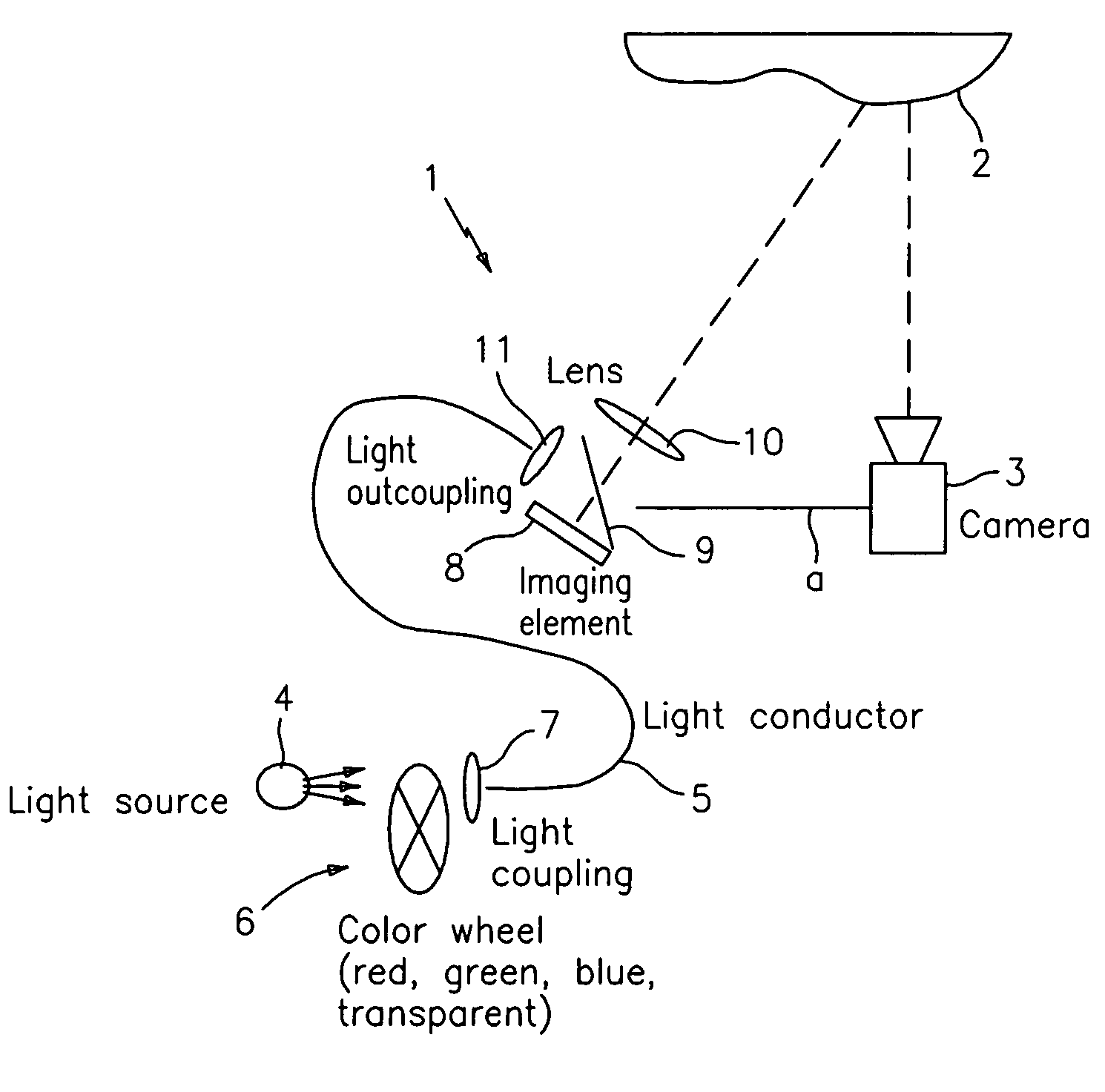
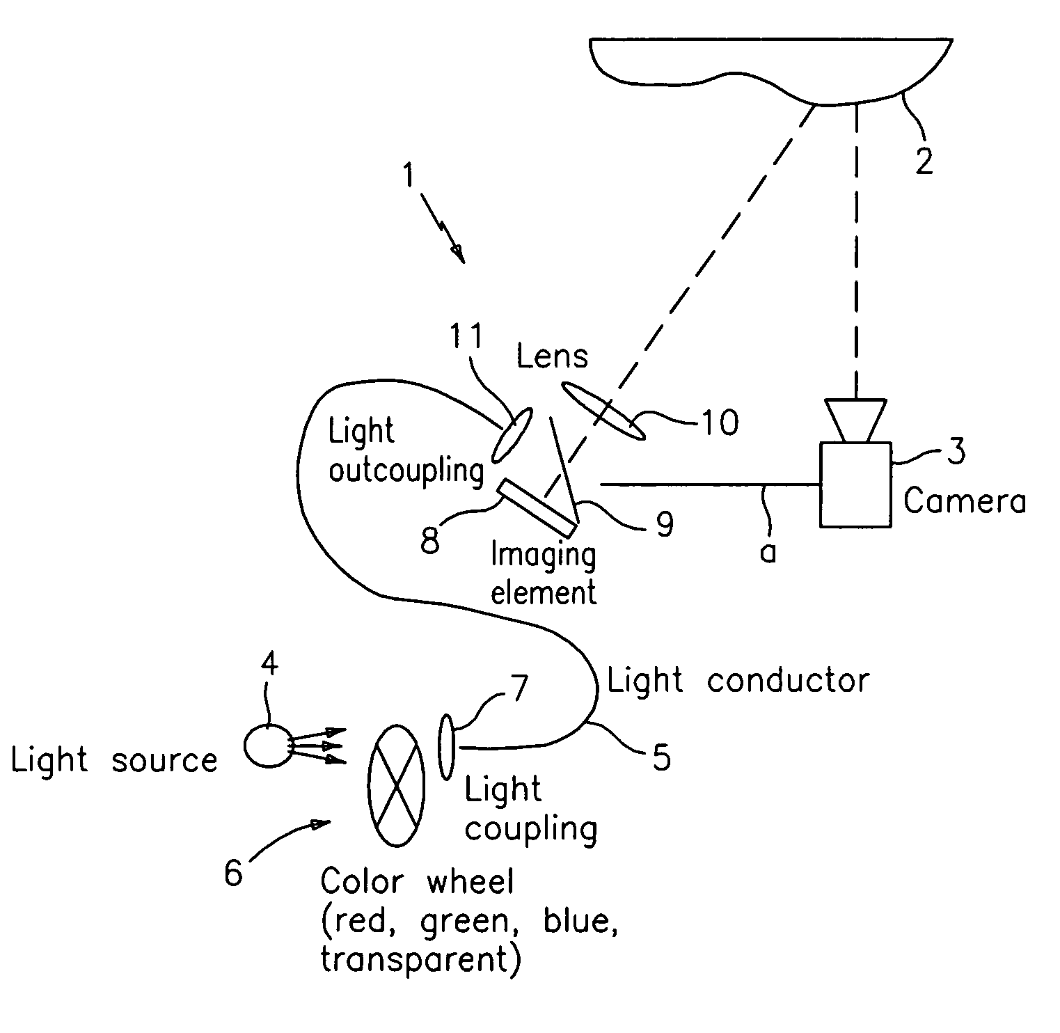
[0028]The apparatus for the determination of the 3D coordinates of an object 2 shown in the only FIGURE includes a projector 1 with which a fringe pattern is projected onto the object 2, a camera 3 for the recording of the light reflected by the object 2 and an evaluation unit, not shown in the drawing, for the evaluation of the recorded images. The projector 1 includes an imaging element 8, a mirror 9 and a lens 10. The imaging element 8 is in particular an LCOS display, a mirror array or an LCD display.

[0029]The light for the projector 1 originates from a light source 4 whose light is supplied to the projector 1 via a light conductor, in particular a liquid light conductor 5. The light from the light source 4 is coupled into the liquid light conductor 5 via a light coupling 7 and is cast onto the mirror 9 via a light outcoupling 11 which reflects it onto the imaging element 8 from where it is projected through the lens 10 onto the object 2. A color wheel 6 is provided between the ...


PUM


Abstract

A method serves for the determination of the 3D coordinates of an object (2). A fringe pattern is projected onto the object (2) in the method. The light reflected by the object (2) is recorded and evaluated. To improve such a method, the fringe pattern is projected onto the object (2) by an imaging element (only FIGURE).

Description

BACKGROUND OF THE INVENTION[0001]The invention relates to a method for the determination of the 3D coordinates of an object and to an apparatus for the carrying out of such a method.[0002]Optical 3D measuring methods for the determination of the 3D coordinates of an object are already known. In this connection, the methods of active, pictorial triangulation are much superior to other measuring methods with respect to data quality and measuring speed. In the methods of active, pictorial triangulation, the object to be measured is illuminated using one or more fringe patterns and is observed using one or more cameras, in particular digital area scan cameras, at one or more specific angles for the projection of the fringe pattern. Fringe patterns of different direction, frequency (fringe spacing, period) and / or amplitude development can be used.[0003]The calculation of the 3D coordinates (3D data) of the measured object usually takes place in an evaluation computer via the evaluation o...

Claims


Application Information

Patent Timeline
Patent Type & Authority Patents(United States)
IPC IPC(8): G01B11/24
CPCG01B11/2513
Inventor STEINBICHLER, MARKUSMAYER, THOMASESTERMANN, MARKUS
Owner CARL ZEISS OPTOTECHN GMBH
Why Eureka
Try Eureka