Rowing simulation machine

a simulation machine and lateral stability technology, applied in the field of rowing simulation machines, can solve the problems of complex mechanisms, high purchase price, and limited level of lateral stability, and achieve the effects of high purchase price, high maintenance cost, and complex mechanisms

Inactive Publication Date: 2009-08-11
ROACH MATTHEW DUNCAN
View PDF15 Cites 21 Cited by
  • Summary
  • Abstract
  • Description
  • Claims
  • Application Information

AI Technical Summary

Problems solved by technology

It uses a gyroscopic flywheel system to provide resistance and a limited level of lateral stability.
These prior art rowing machines present a number of disadvantages including the complexity of their designs.
Complex mechanisms often involve a high level of maintenance and a high purchase price.
Another disadvantage of U.S. Pat. No. 4,743,011 (Coffey), is that the machine presents danger to the user, and others in the vicinity of the machine, by virtue of the swinging cam sector arms.
Yet another disadvantage of the prior art is the large amount of space these machines occupy and the subsequent difficulty associated with their transportation and handling within gymnasiums and rowing sheds.

Method used


Image

  • Rowing simulation machine
  • Rowing simulation machine
  • Rowing simulation machine

Examples


Embodiment Construction

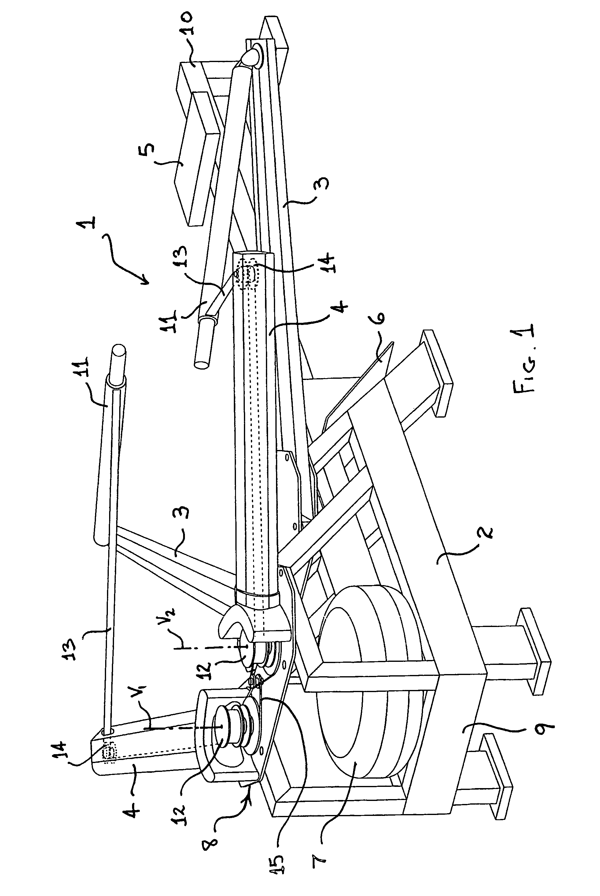
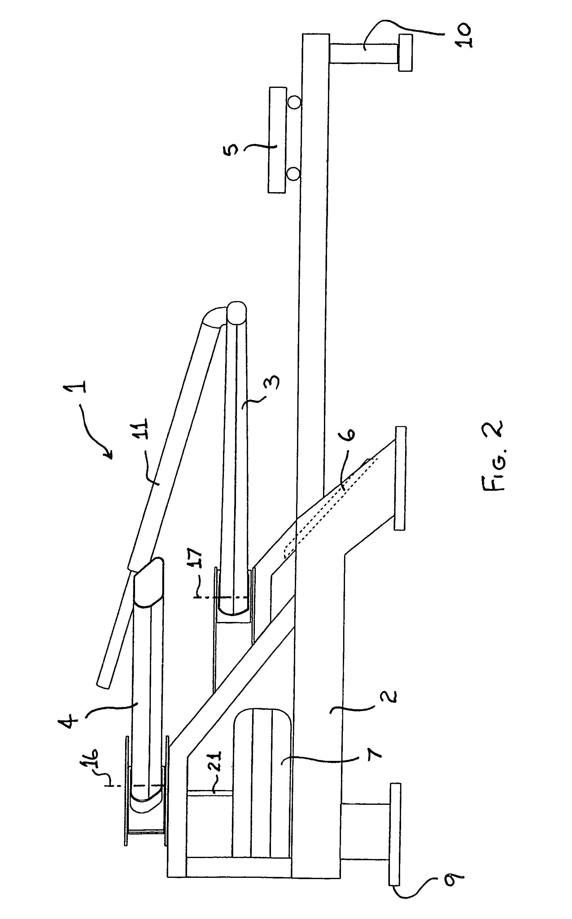
[0029]FIGS. 1 and 2 depict a rowing machine 1 on which a user simulates a rowing or sculling motion. The rowing machine 1 imparts a resistance to the rowing or sculling motion and comprises a frame 2, a pair of outriggers 3, a pair of arms 4, a seat 5, a pair of footrests 6, a flywheel 7 and a drive assembly 8. The frame 2 has a fore end 9 and an aft end 10. The arms 4 are mounted near the fore end 9 of the frame 2, in front of the outriggers 3, above the flywheel 7 and extending laterally away from the frame 2, at about 45 degrees to the longitudinal axis of the frame 2. The outriggers 3 are mounted intermediate the arms 4 and the aft end 10, although they are closer to the arms 4 than the aft end 10 and they extend laterally away from the frame 2. The seat 5 has wheels underneath it that enable it to slide along the aft side of the frame 2, which comprises a horizontally disposed elongate beam of rectangular cross-section. A user may sit on the seat 5 and push with his legs agains...


PUM


Abstract

A rowing machine on which a user simulates a rowing or sculling motion. The machine imparts a resistance to the rowing or sculling motion. The machine comprises a substantially horizontal frame having a fore end and an aft end, a seat moveably mounted on the frame, foot rest means for positioning the user's feet, a flywheel, a pair of outriggers mounted to the frame and extending laterally from said frame. Each outrigger is adapted to pivotally support a rowing oar at or near its free end. Each oar is connected to the flywheel via a drive assembly. The flywheel is mounted at or near the fore end of said frame and said flywheel has an axis of rotation that is disposed substantially vertically.

Description

CROSS-REFERENCE TO RELATED APPLICATION[0001]This application is a national phase application of International Application No. PCT / AU2004 / 001252 filed on Sep. 15, 2004, and claims priority of Australian provisional patent application Ser. No. 2003905050 filed Sep. 15, 2003.BACKGROUND OF THE INVENTION[0002]1. Field of the Invention[0003]The present invention relates to rowing machines and in particular to a rowing simulation machine.[0004]2. Description of the Prior Art[0005]Rowing machines are well-known for the purposes of building up general fitness and / or for training specifically for rowing and related sports. Rowing machines allow the user to exercise both upper body and lower body strength by simulating roughly the movement required to propel a rowboat through the water.[0006]There is a variety of prior art rowing machines including a rowing simulator disclosed in U.S. Pat. No. 5,779,600 (Pape) utilizing a flywheel that is driven by a pair of oars. U.S. Pat. No. 4,743,011 (Coff...

Claims


Application Information

Patent Timeline
Patent Type & Authority Patents(United States)
IPC IPC(8): A63B69/06A63B71/00A63B21/22
CPCA63B22/0076A63B21/225A63B2022/0084
Inventor ROACH, MATTHEW DUNCAN
Owner ROACH MATTHEW DUNCAN
Why Eureka
Try Eureka