Method for formatting images for angle-specific viewing in a scanning aperture display device

a scanning aperture display and angle-specific technology, applied in the field of multi-dimensional image reproduction, can solve the problems of little flexibility in the number of angles used and the resolution of images to be formatted, and achieve the effect of improving the quality of images and reducing the number of angles

Inactive Publication Date: 2009-08-11
HARTKOP DAVID +1
View PDF60 Cites 37 Cited by
  • Summary
  • Abstract
  • Description
  • Claims
  • Application Information

AI Technical Summary

Problems solved by technology

Current methods for formatting images for autostereoscopic display offer little flexibility in terms of the number of angles used and the resolution of the images to be formatted.

Method used


Image

  • Method for formatting images for angle-specific viewing in a scanning aperture display device
  • Method for formatting images for angle-specific viewing in a scanning aperture display device
  • Method for formatting images for angle-specific viewing in a scanning aperture display device

Examples


Embodiment Construction

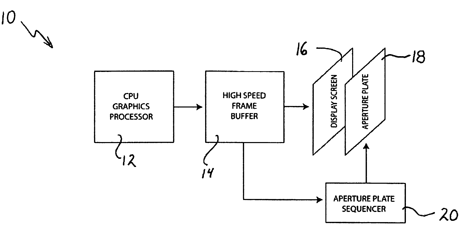
[0046]Referring to the block diagram of FIG. 1, there is shown a general depiction of the scanning aperture three dimensional display system 10 according to an embodiment of the invention. In a basic form, the system includes a central processing unit / graphic processor 12, a high speed frame buffer 14, a display screen 16, an aperture plate 18 and an aperture plate sequencer 20.

[0047]The embodiment of FIG. 1 is a solid state example of the invention, having no moving parts. In accordance with various embodiments, described herein, the display screen 16, aperture plate 18, aperture plate sequencer 20 and other hardware / software components can be implemented in many different ways without departing from the spirit of the invention. In accordance with other embodiments, the apertures in the aperture plate 18 can be of different configuration. These embodiments are discussed in detail below, however a brief explanation of the operating principles and considerations in the implementation...


PUM


Abstract

A method for formatting images for angle specific viewing in a scanning aperture dimensional display device. Input images are rearranged into slices or sections to create a set of output images. The images derived from the output images are formed by rearranging the image slices or sections and disposing the image to be viewed directly behind an open aperture in an aperture plate in a scanning aperture display device. By cycling the images in relation to the cycling of the open apertures of the aperture plate, angle specific viewing of the scanning aperture display can be provided. The number angles for angle specific viewing can be varied and can range from 2-1000 distinct viewing angles from a single scanning aperture display device.

Description

CROSS REFERENCE TO RELATED APPLICATIONS[0001]This application is a Continuation in Part of co-pending U.S. patent application Ser. No. 10 / 817,592 filed Apr. 2, 2004.BACKGROUND OF THE INVENTION[0002]1. Field of the Invention[0003]The present invention relates to multi dimensional image reproduction, and more particularly, it relates to a method for angle specific viewing in an image reproduction device such as a scanning aperture device.[0004]2. Description of the Prior Art[0005]Various approaches to 3D image reproduction have been experimented with and implemented in different aspects of industrial life. Many of today's current imaging applications are requiring of more detail and the ability to “look around” or see all sides of an image in true 3D representation. Some exemplary applications for such imaging include Medical, Military and other industrial and recreational fields.[0006]Angle specific viewing of images allows one display device to display different images to different ...

Claims


Application Information

Patent Timeline
Patent Type & Authority Patents(United States)
IPC IPC(8): G09G5/12G09G5/42G02B30/31G06T15/00G06T17/00H04N13/00
CPCH04N13/0409G02B27/2214H04N13/31G02B30/31G02B30/27
Inventor HARTKOP, DAVIDDUNN, JASON
Owner HARTKOP DAVID
Why Eureka
Try Eureka