Two-stroke internal combustion engine

a two-stroke, internal combustion technology, applied in the direction of liquid fuel feeders low-pressure fuel injection, etc., to achieve the effect of increasing construction expenditur

Inactive Publication Date: 2009-08-18
KIRCHBERGER ROLAND
View PDF16 Cites 6 Cited by
  • Summary
  • Abstract
  • Description
  • Claims
  • Application Information

AI Technical Summary

Benefits of technology

[0004]The object underlying the invention is therefore to configure a two-stroke internal combustion engine of the type described in the introduction such that fuel-air mixing dependent on engine loading is possible in either the crankcase or the cylinder, without the increased construction expenditure as a result of separate injection nozzles having to be accepted.
[0006]The conveying distance of the injected fuel depends, according to the orientation of the injection nozzle in the direction of the inlet region of the transfer passage issuing from the air intake manifold, on the air flow prevailing in the region of the injection nozzle and therewith on the direction of movement of the piston and control of the transfer passage through the piston. If, during the compression stroke of the piston, air is drawn into the crankcase by way of the air intake manifold, the fuel injected toward the inlet region of the transfer passage is carried along with the drawn-in air into the crankcase for fuel-air mixing. However, in the case of fuel injection at the end of the power stroke of the piston, the fuel, when the transfer passage is open, is carried along with the air conveyed from the crankcase via the transfer passage into the cylinder, so air-fuel mixing can take place in the transfer passage and in the cylinder in a delayed manner for scavenging. By selecting the injection interval as a function of the direction of movement of the piston and the controller of the transfer passage, fuel-air mixing can take place, depending on the engine speed or the engine loading, inside the crankcase or outside it in order to keep the scavenging losses low on the one hand and to ensure good speed strength on the other hand.
[0007]Particularly simple construction conditions result in this connection if the injection nozzle is arranged on the peripheral side of the air intake manifold opposing the inlet region of the transfer passage. In this case the spray cone of the injection nozzle extends transversely to the air intake manifold, and this creates advantageous flow conditions for carrying along the injected fuel both when drawing the air into the crankcase and when transferring the drawn-in air into the cylinder.

Problems solved by technology

However, in the case of fuel injection at the end of the power stroke of the piston, the fuel, when the transfer passage is open, is carried along with the air conveyed from the crankcase via the transfer passage into the cylinder, so air-fuel mixing can take place in the transfer passage and in the cylinder in a delayed manner for scavenging.

Method used


Image

  • Two-stroke internal combustion engine
  • Two-stroke internal combustion engine
  • Two-stroke internal combustion engine

Examples


Embodiment Construction

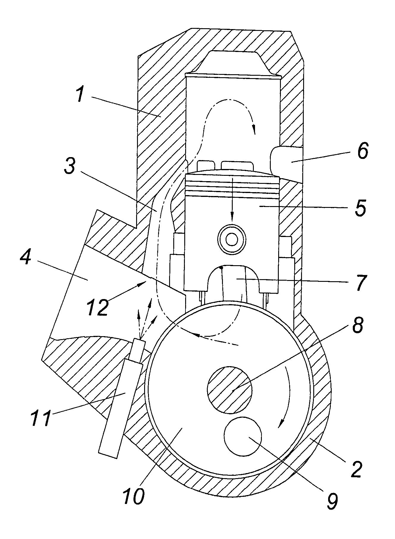
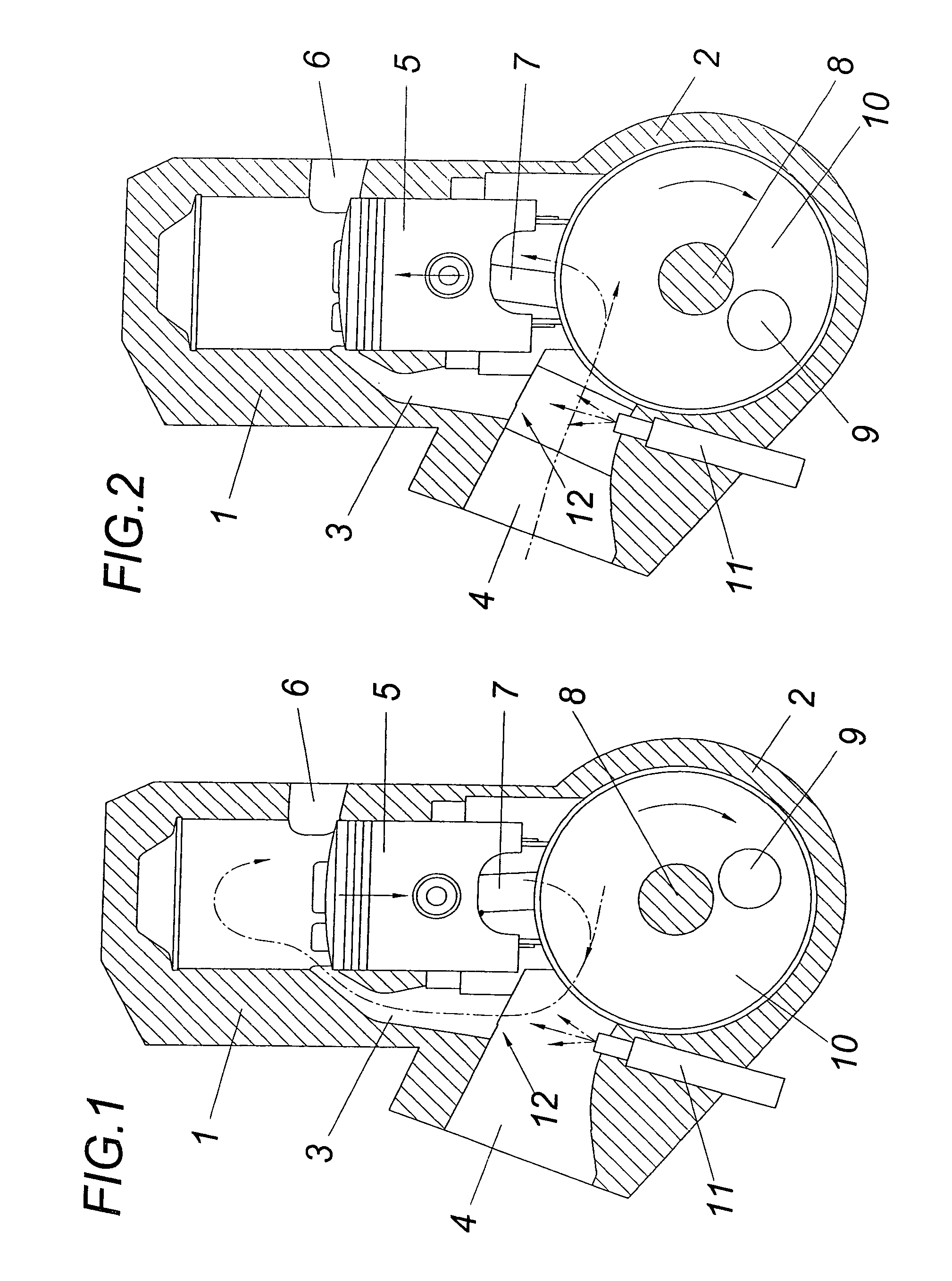
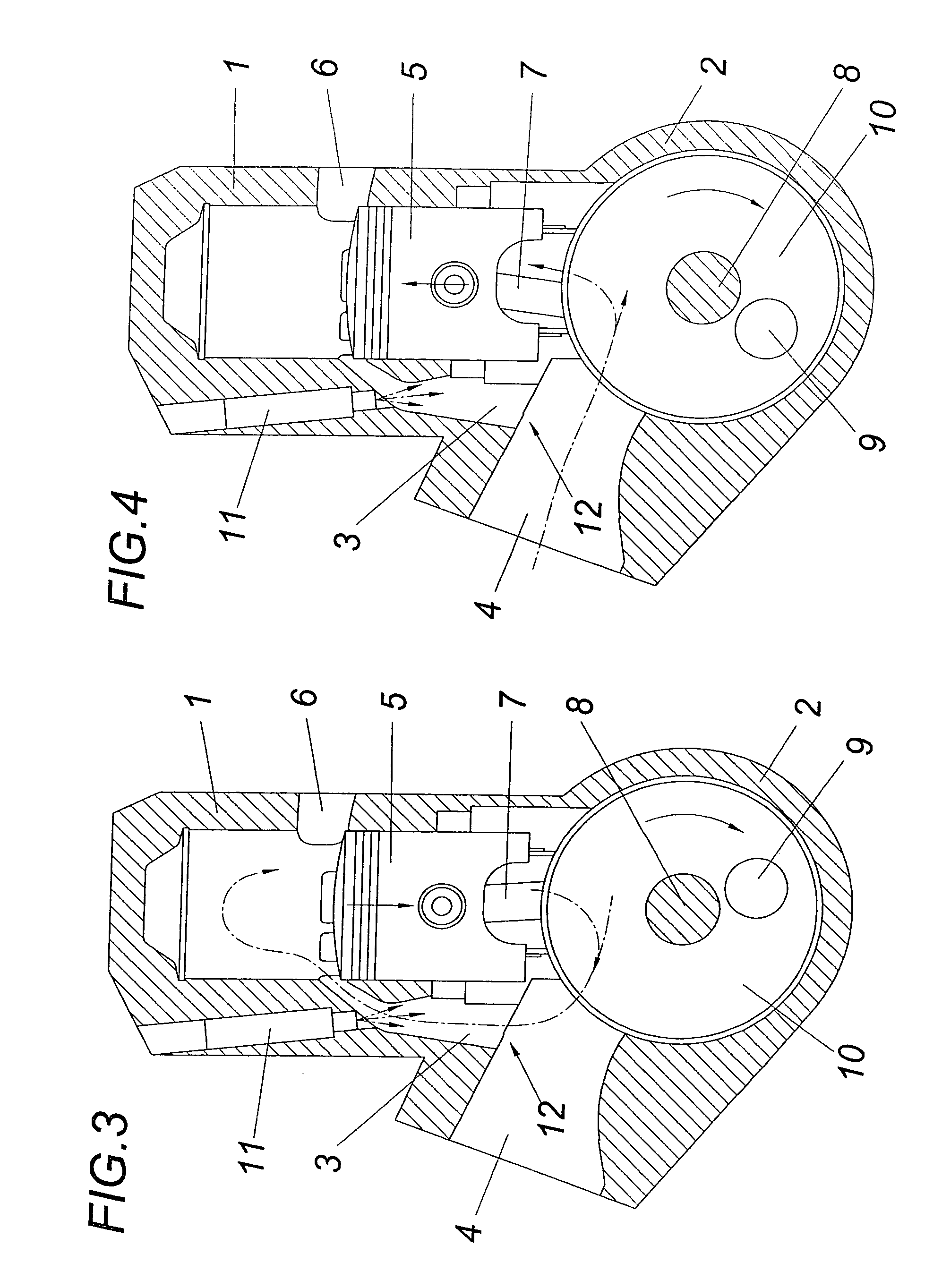
[0016]The two-stroke internal combustion engine according to FIGS. 1 and 2 comprises at least one cylinder 1 which, together with a crankcase 2, forms a motor unit. Provided between the crankcase 2 and the cylinder 1 is at least one transfer passage 3 which issues from the air intake manifold 4 via which air is drawn into the crankcase 2 by way of a non-return valve connected upstream and, more precisely, with the aid of the crankcase pump produced by the piston 5. The piston 5, which is guided in the cylinder 1 and controls the transfer passage 3 and optionally provided additional transfer passages and the outlet passage 6, is conventionally connected by a connecting rod 7 to a crankshaft 8 mounted in the crankcase 2, the crank webs of which crankshaft, which receive the crank pins 9 for mounting the connecting rod 7, are designated 10.

[0017]An injection nozzle 11 which is controlled by a controller (not shown) is used for injecting fuel. This injection nozzle 11 is arranged on the...


PUM


Abstract

A two-stroke internal combustion engine with at least one cylinder (1), comprising a crankcase (2) flow-connected to the cylinder (1) by at least one transfer passage (3) and provided with an air intake manifold (4) and comprising an injection device for optional introduction of a fuel into the cylinder (1) or the crankcase (2) is described. To achieve fuel-air mixing adapted to the operating state of the engine it is proposed that the injection device comprises at least one injection nozzle (11) which is oriented toward the inlet region (12) of the transfer passage (3) issuing from the air intake manifold (4) and can be controlled as a function of the direction of movement of the piston (5) and the controller of the transfer passage (3).

Description

CROSS REFERENCE TO RELATED APPLICATIONS[0001]Applicant claims priority under 35 U.S.C. §119 of Austrian Application No. A 1241 / 2004 filed Jul. 21, 2004. Applicant also claims priority under 35 U.S.C. §365 of PCT / AT2005 / 000256 filed Jul. 8, 2005. The international application under PCT article 21(2) was not published in English.FIELD OF THE INVENTION[0002]The invention relates to a two-stroke internal combustion engine with at least one cylinder, comprising a crankcase flow-connected to the cylinder by at least one transfer passage and provided with an air intake manifold and comprising an injection device for optional introduction of a fuel into the cylinder or the crankcase.DESCRIPTION OF THE PRIOR ART[0003]To reduce the scavenging losses in two-stroke internal combustions engine with fuel-air mixing by injection of fuel into the fresh air drawn into the crankcase, the fuel can either be injected into the cylinder in the region of the transfer passage, in the case of transfer of th...

Claims


Application Information

Patent Timeline
Patent Type & Authority Patents(United States)
IPC IPC(8): F02B25/00F02M69/10F02B25/02F02B33/04F02B75/02F02B75/12F02M69/04
CPCF02B25/02F02M69/045F02M69/10F02M69/044F02B2075/025F02B2075/125Y02T10/123Y02T10/12
Inventor KIRCHBERGER, ROLAND
Owner KIRCHBERGER ROLAND
Why Eureka
Try Eureka