Stand structure of an LED Christmas lamp

a technology of led christmas lamps and stand structures, which is applied in the direction of two-part coupling devices, electrical discharge tubes, coupling device connections, etc., can solve the problems of increasing operation time, waste of manufacturing costs, and inability to meet the needs of the application

Inactive Publication Date: 2009-08-18
HSU FU HSIEN
View PDF5 Cites 86 Cited by
  • Summary
  • Abstract
  • Description
  • Claims
  • Application Information

AI Technical Summary

Problems solved by technology

However, there is deficiency existed in this practical application.
This is merely increasing the operation time, and even the assembly is unable to be accomplished then the manufacturing cost is wasted.
However, there is the same deficiency existed in this practical application as the aforementioned known lamp stand.
This is merely increasing the operation time, and even the assembly is unable to be accomplished then the manufacturing cost is wasted.

Method used


Image

  • Stand structure of an LED Christmas lamp
  • Stand structure of an LED Christmas lamp
  • Stand structure of an LED Christmas lamp

Examples


Embodiment Construction

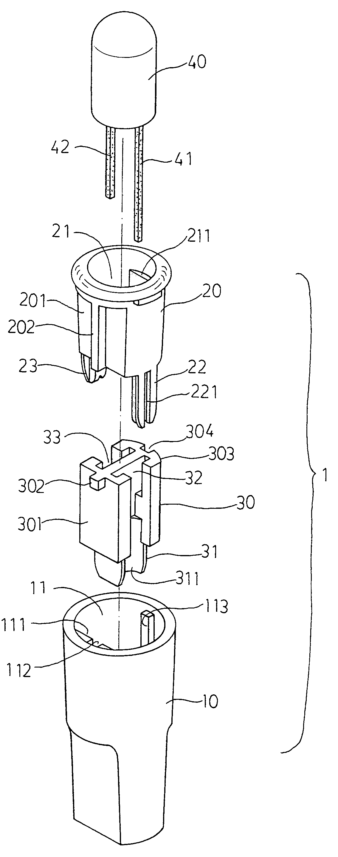
[0015]Please refer to those shown in FIGS. 5 and 6. The lamp stand 1 of the present invention is composed of a main stand 10, a supporting stand 20, and a conductive lead stand 30. A shallow containing groove space 11 is formed in the said main stand 10. A positioning protruding surface 111 equipped with the long concave groove 112 is formed in the front side of the shallow containing groove space 11, and a protruding bar 113 is formed in the relative rear side of the shallow containing groove space 11. A compartment groove stand 31 is extended in the bottom of the conductive lead stand 30, whose left and right faces each form with a bar typed opening and form inward separate T typed containing grooves 32, 33. Furthermore, a positioning cutting surface 301 with a protruding bar 302 on top is formed in the front side of the conductive lead stand 30, and an arc shaped protruding positioning edge 303 with a concave groove 304 in the middle is formed on the upper edge of the rear side s...


PUM


Abstract

An LED Christmas lamp has the lamp stand composed of a main stand, a supporting stand and a conductive lead stand. A positioning protruding surface with a long concave groove is formed in the front side of the containing groove space, and a protruding bar is formed in the relative rear side of the containing groove space. A smaller compartment groove stand is extended in the bottom of the conductive lead stand. An arc shaped protruding groove surface is formed on the joint surface of the compartment stand and containing groove. A lamp laying groove space with protruding stop surfaces in its front and rear sides are formed inside the supporting stand. A positioning cutting surface with a long protruding bar is formed in the front side of the supporting stand and a concave groove is set in the rear side. Then, they are laid in the main stand to let the two pins of LED to be stick with the conductive copper plates of the two power conductive leads smoothly.

Description

FIELD OF THE INVENTION[0001]The present invention is related to an improved technology about Christmas lamp products, and especially is in accordance with an improved technology designed for the lamp stand structure of a kind of LED typed Christmas lamp.BACKGROUND OF THE INVENTION[0002]The current known LED typed Christmas lamp stands generally have two kinds of patterns as shown in FIG. 1 (U.S. Pat. No. 6,120,312) and FIG. 3 (U.S. Pat. No. 6,183,310). Please refer to the first kind of known lamp structure shown in FIGS. 1 and 2, which is a lamp stand without soft core. The structure mainly integrates an LED 40 with a lampshade 90 directly, and cooperates with a lamp stand 70 composed of an internal seat 71 and an external seat 72. Two sides of the said internal seat 71 are set with a wire bestowing groove 711, which is able to lay two power conducting leads 50, and set with chasms 712 at two sides of the groove for clipping of conductive copper plates 51. Cylindrical supporting por...

Claims


Application Information

Patent Timeline
Patent Type & Authority Patents(United States)
IPC IPC(8): H01R33/00
CPCH01R33/09
Inventor HSU, FU-HSIEN
Owner HSU FU HSIEN
Why Eureka
Try Eureka