
System for providing lumbar motion and support

a technology of lumbar spine and motion support, which is applied in the direction of operating chairs, gymnastics exercise, chairs, etc., can solve the problems of user placing an enormous amount of stress on the spine, severe back pain, fatigue,

Inactive Publication Date: 2009-08-25
HAZARD ROWLAND G
View PDF23 Cites 14 Cited by
  • Summary
  • Abstract
  • Description
  • Claims
  • Application Information

AI Technical Summary

Benefits of technology

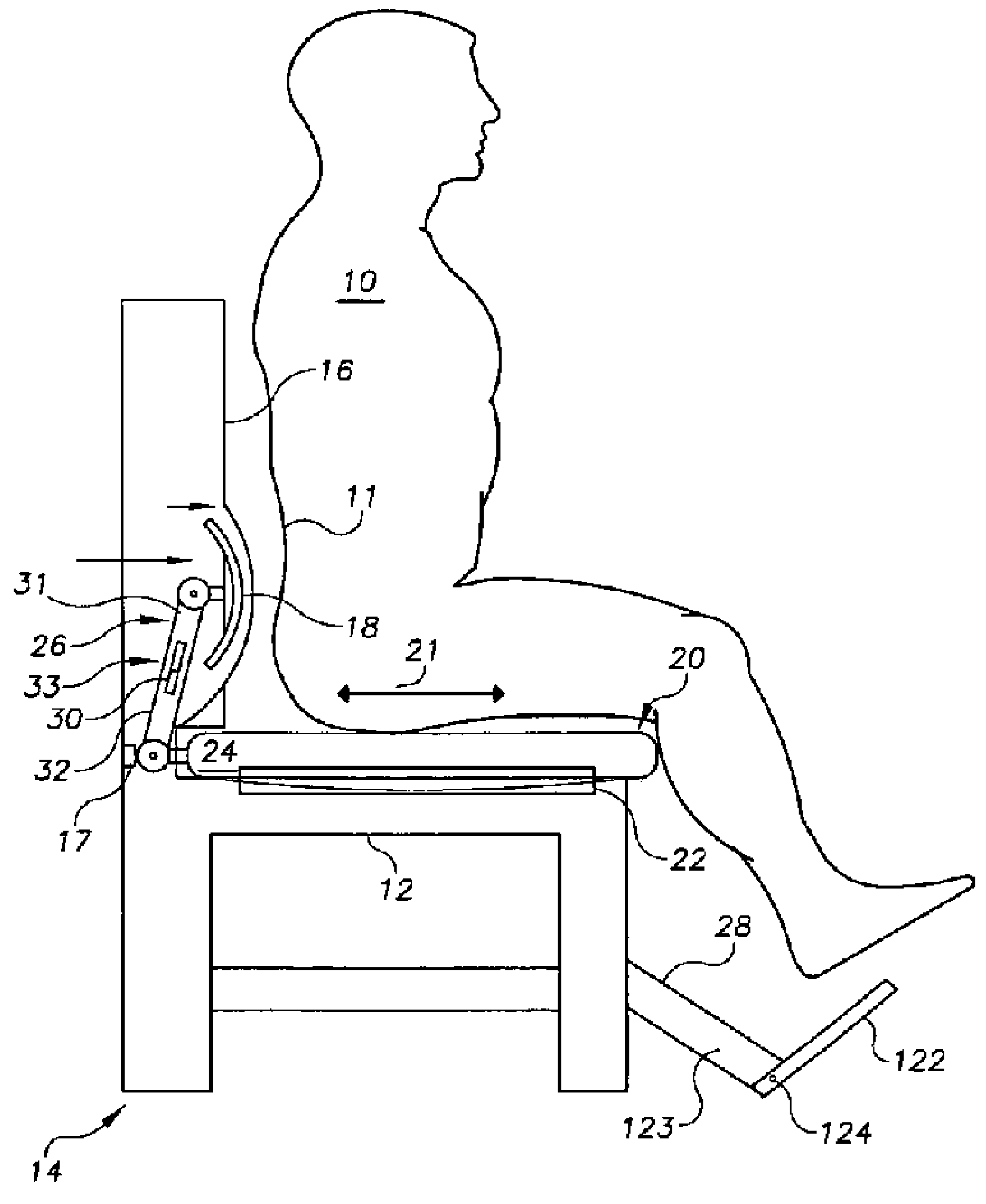
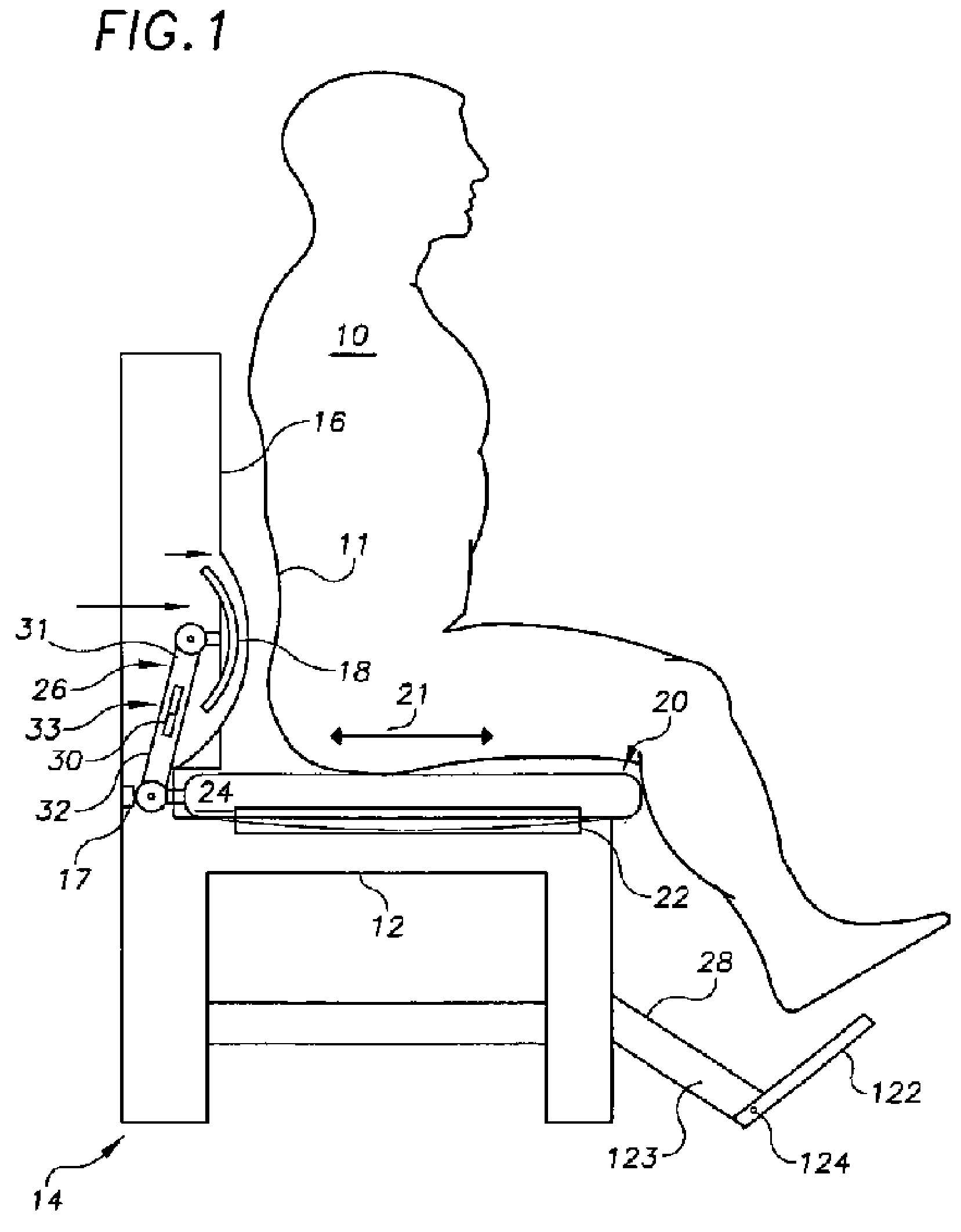
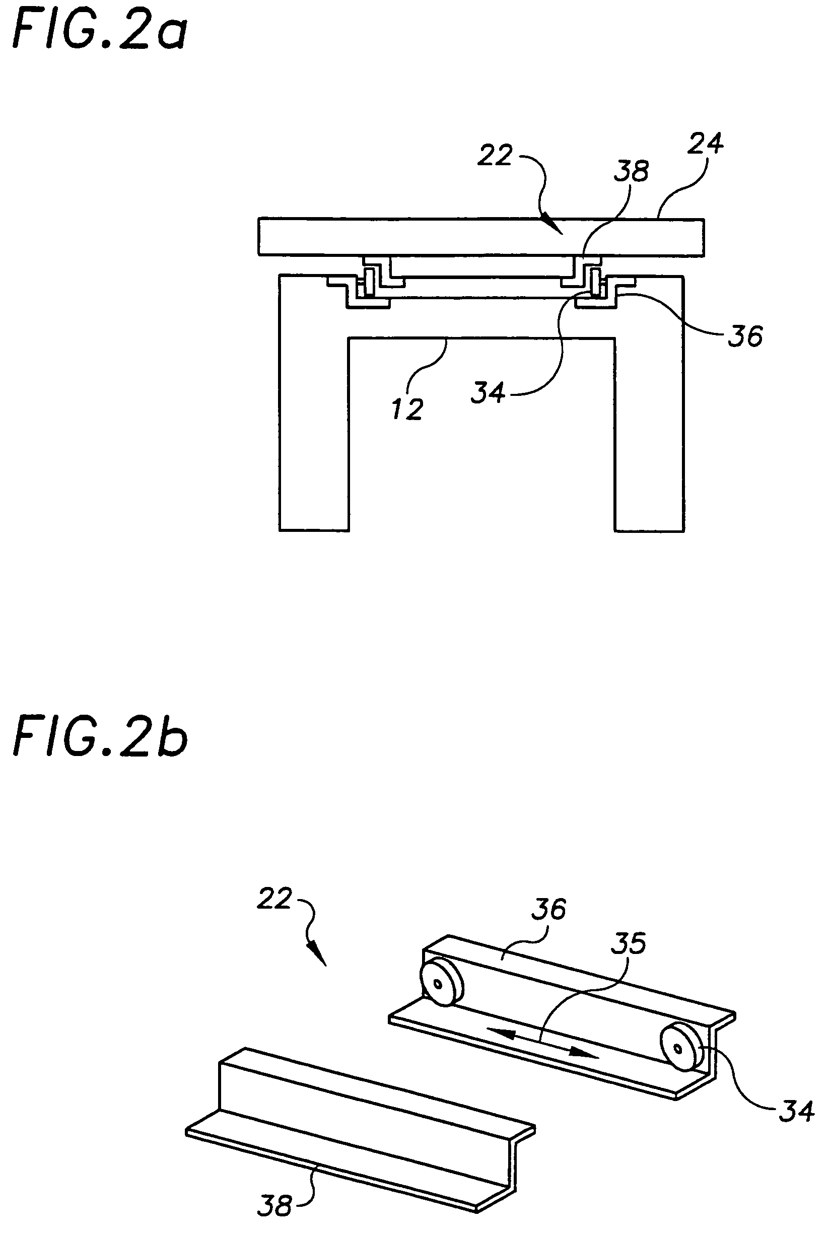
"The present invention is a seating system that provides support and motion to the lumbar region of the spine. The system allows users to control the pressure and support applied to the spine while in a seated position. It includes a static structure, a moving seat pan, and a force applying means. The force applying means can be adjusted to the user's needs and can be powered by the user's lower extremities or electronically. The seat pan can move along a track or glide along a glider assembly, and its movement can be adjusted to tilt forward or backward. The system can also include a means for adjusting the correlation between the movement of the seat pan and the force applying means. The force applying means can include a pump, rack and pinion arrangement, mechanical cam arrangement, or gear and cable arrangement to translate the force supplied by the moving apparatus into the force delivered to the user's back. Overall, the invention provides a more comfortable and customizable seating system for promoting spinal health."

Problems solved by technology

A user places an enormous amount of stress on the spine when situated in a seated position.
Prolonged sitting in the same position can cause fatigue, stiffness and severe back pain due to stress and strain on the ligaments and intervertebral disks of the spine.

Method used


Image

  • System for providing lumbar motion and support
  • System for providing lumbar motion and support
  • System for providing lumbar motion and support

Examples


Embodiment Construction

[0036]Preferred embodiments of the invention will now be described with reference to the accompanying drawings. A seating system according to the present invention comprises a substantially static structure adjacent to the back of a user, a moving apparatus adjacent to the buttocks and thighs of the user supplying a motive force, a force applying means disposed between the static structure and the back of the user, the force applying means including a back engaging surface for increasing and decreasing a force applied to the back of the user in response to the supplied motive force, and a means for locking the moving apparatus in place. Numerous embodiments employing different support structures for the moving apparatus and / or means for translating the motive force supplied by the moving apparatus into a force applied to the back of the user are described below for conveying the concepts of the invention and are not intended to be limiting in any manner.

[0037]Referring now to the fi...


PUM


Abstract

A seating system for providing spinal motion and support. The system comprising a substantially static structure adjacent to the back of a user, a moving apparatus supplying a motive force, wherein the moving apparatus is adjacent to the buttocks and thighs of the user and is powered by the lower extremities of the user, a force applying structure disposed between the static structure and the back of the user, the force applying apparatus including a back engaging surface for increasing and decreasing a force applied to the back of the user in response to the supplied motive force, and a structure for locking the moving apparatus in place. Various embodiments of moving apparatus, force applying structure, and locking and / or motion limiting structure are presented.

Description

[0001]This application is a continuation of U.S. patent application Ser. No. 09 / 957,205 filed Sep. 20, 2001, now abandoned, and entitled “System for Providing Lumbar Motion and Support,” the contents of which are incorporated herein by reference.FIELD OF THE INVENTION[0002]The present invention relates generally to a system and method for providing motion and support to the lumbar region of the spine. In particular, the invention provides a moving seat apparatus that increases and decreases pressure applied to the lumbar region of the spine.BACKGROUND OF THE INVENTION[0003]A user places an enormous amount of stress on the spine when situated in a seated position. Prolonged sitting in the same position can cause fatigue, stiffness and severe back pain due to stress and strain on the ligaments and intervertebral disks of the spine. Supporting the lumbar curve of the spine reduces the load on the low back muscles. Lumbar supports, such as cushions, bladders and mechanical devices, have...

Claims


Application Information

Patent Timeline
Patent Type & Authority Patents(United States)
IPC IPC(8): A47C1/00A47C3/00A47C7/36A47C7/40A47C1/031A47C1/032A47C3/02A47C7/46A47C9/00A61H1/00A61H1/02A61H23/04
CPCA47C3/0255A47C7/46A47C9/002A61H1/0292A61H9/0085A47C7/506A47C1/023A61H2201/1269A61H2205/081A61H2209/00A61H2201/0149
Inventor HAZARD, ROWLAND G.
Owner HAZARD ROWLAND G
Learn More