Sweep style conduit bodies

a conduit body and weep technology, applied in the field of conduit bodies, can solve the problems of reducing the usable interior capacity of the conduit body, adversely affecting the performance of the cable,

Active Publication Date: 2009-09-01
THOMAS & BETTS INT INC
View PDF21 Cites 11 Cited by
  • Summary
  • Abstract
  • Description
  • Claims
  • Application Information

AI Technical Summary

Benefits of technology

[0009]A conduit body device accommodates wires therethrough. The device includes a conduit body having a body wall including an elongate side wall, a bottom wall, and an open end defining a body interior. The body includes at least one hub extending from the body wall in communication with the body interior. The hub includes a hub wall defining an access channel for passage of the wire therethrough. The hub wall includes a guide surface outwardly of said body wall and protruding into the channel for maintaining a bend radius of the wire passing from the body interior through the channel.

Problems solved by technology

In certain situations, especially with the use of communications cables such as data cable and fiber optic cable, placing a small bend radius on the cable to effect the change in direction may adversely effect the performance of the cable.
While this device may serve adequately to effect a desirable change in direction, the inwardly extending projection does provide an obstruction to the pulling of the wire through the conduit body and also reduces the usable interior capacity of the conduit body.

Method used


Image

  • Sweep style conduit bodies
  • Sweep style conduit bodies
  • Sweep style conduit bodies

Examples


Embodiment Construction

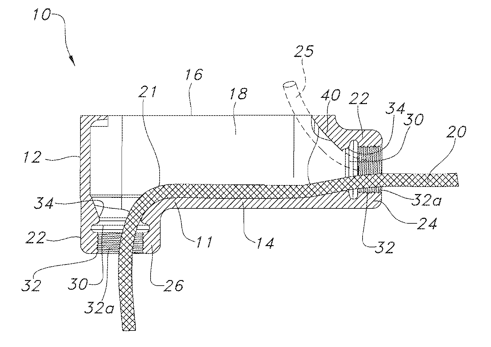
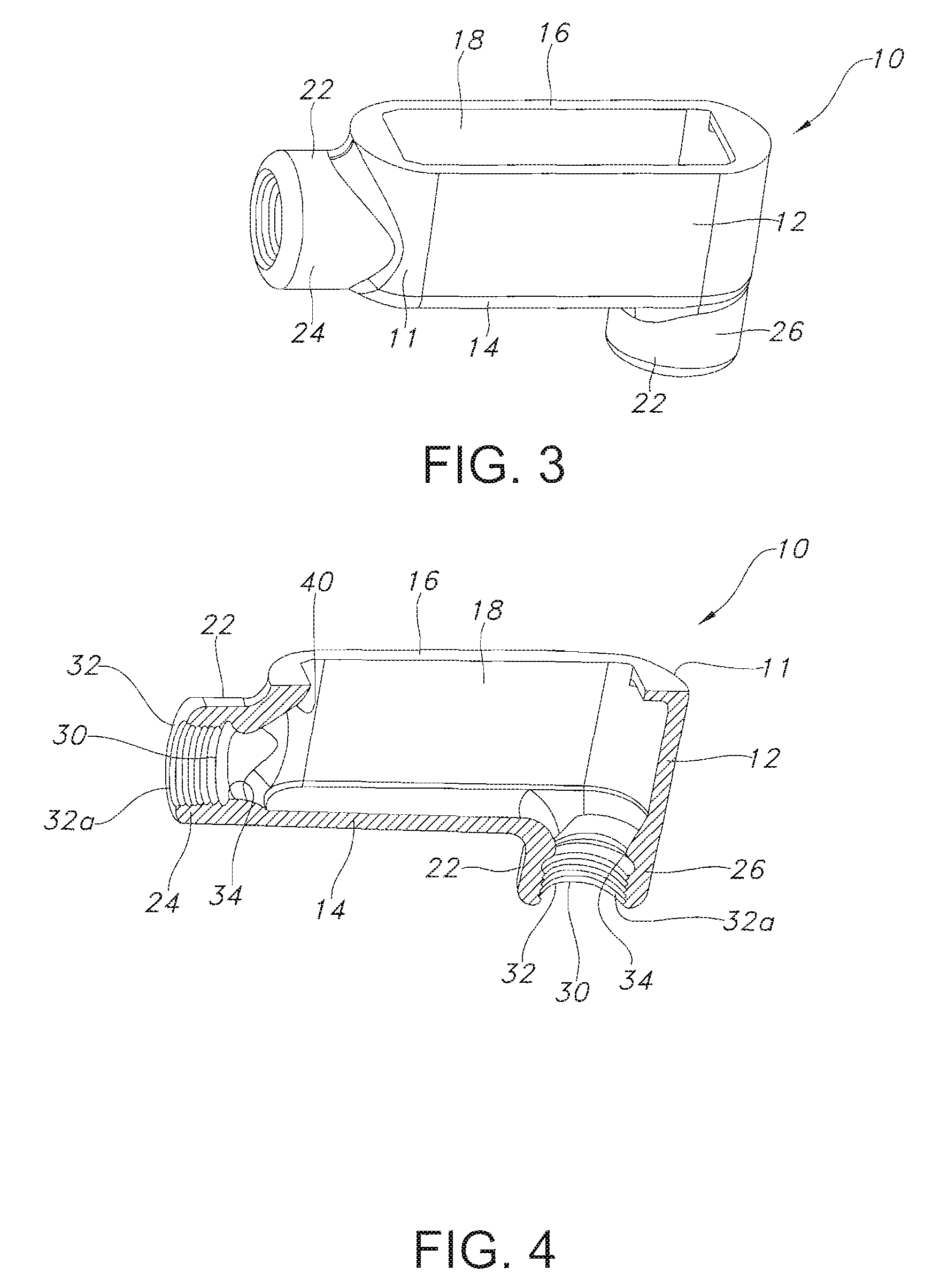
[0016]The present invention provides a conduit body for use in electrical systems, including electrical conduit systems, where electrical wire and cables are run through various structures. The conduit body which is used in conduit systems allows the wires to be pulled through the conduit system and also effects changes of direction in the system.

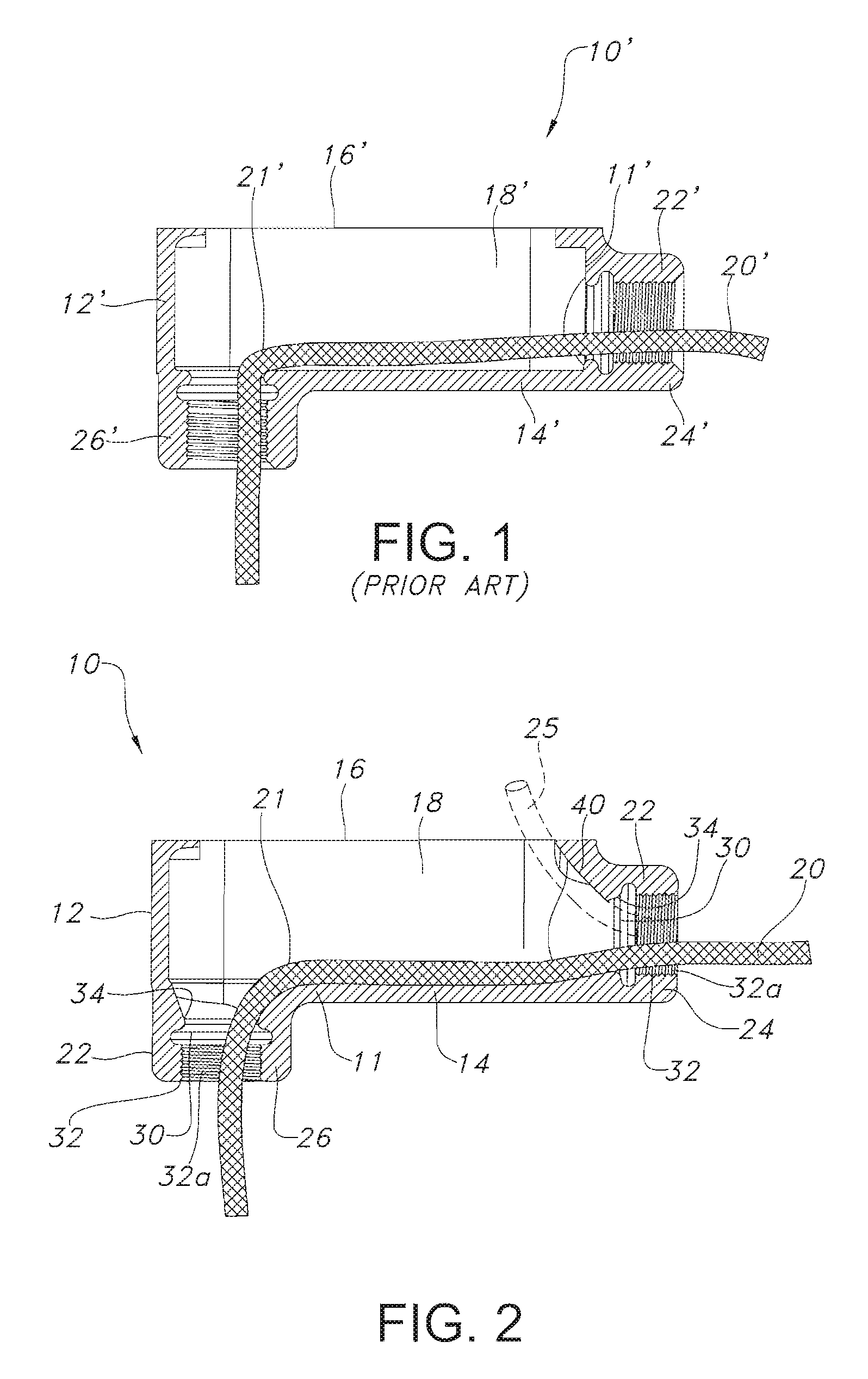
[0017]FIG. 1 shows a conventional conduit body 10′ currently used in conduit systems. Conduit body 10′ is generally an elongate tubular shaped member generally formed of a material which, matches the conduit employed in the system. A typical conduit body is formed of metal or rigid plastic.

[0018]A conduit body 10′ includes a conduit body wall 11′ including an upwardly extending perimetrical side wall 12′ having a closed bottom wall 14′ and an opposed open end 16′. The open upper end 16′ may be closed with a removable cover (not shown) which allows access to the interior 18′ of conduit body 10′.

[0019]In order to provide passage of wire 20′ t...


PUM


Abstract

A conduit body provides for the accommodation of wire extending therethrough. The conduit body includes a body wall having an elongate side wall, a bottom wall and an open end defining a body interior. At least one hub extends from the body wall in communication with the body interior. The hub includes a hub wall defining an access channel for passage of wire therethrough. The hub wall includes a guide surface outwardly of the body wall and protruding into the channel for maintaining a bend radius of the wire passing from the body interior through the channel.

Description

CROSS-REFERENCE TO RELATED APPLICATION[0001]This application claims priority to U.S. Provisional Patent Application No. 60 / 966,451, filed on Aug. 28, 2007, herein incorporated by reference.FIELD OF THE INVENTION[0002]The present invention relates generally to a conduit body containing electrical wires, and more particularly, relates to a conduit body which facilitates the passage of wires and cables therethrough.BACKGROUND OF THE INVENTION[0003]Electrical conduit systems are required in order to safely provide electrical power to industry, homes, commercial buildings and the like. These conduit systems often include long runs of rigid electrical conduit with frequent changes in direction, such as 90° turns. Conduit bodies are typically installed in the conduit systems at various locations, both to provide access to the wires and to route the wires along the conduit path. Often, the change of direction in the conduit is accomplished in the conduit body.[0004]Conventional conduit bodi...

Claims


Application Information

Patent Timeline
Patent Type & Authority Patents(United States)
IPC IPC(8): H02G3/04
CPCH02G3/06H02G9/04H02G3/081
Inventor PYRON, ROGER D.
Owner THOMAS & BETTS INT INC
Why Eureka
Try Eureka