Multifunctional lock

a multi-functional, lock technology, applied in the direction of cylinder locks, building locks, construction, etc., can solve problems such as potential security hazards

Active Publication Date: 2009-09-08
MALAFON ELECTRONICS SUZHOU
View PDF18 Cites 28 Cited by
  • Summary
  • Abstract
  • Description
  • Claims
  • Application Information

AI Technical Summary

Benefits of technology

[0004]It's the object of the present utility model to provide a multifunctional lock which allows the key to be changed many times and has no potential security hazard.
[0011]With the application of the technical solution described above, the present utility model has the following advantages over the prior art: in the solution, the tooth pieces engage with the sliding blocks for most of the time during the rotation of lock core, and only when the lock core is rotated into the proper position where the projection on the unit is settled into the cut on the lock shell and because of the of the second elastic element the support for sliding blocks moves downwards with the unit, and the sliding blocks placed on the support for sliding blocks disengage from the tooth pieces initially engaged therewith, at this time the original key can be removed and changed into a new key, thus eliminating the potential security hazard.

Problems solved by technology

China Patent No. 200320123249.4 discloses a lock which allows the key to be changed, wherein the original key can be removed at any position of the rotation of the lock core and changed by a new key in the unlocked condition, thus causing a potential security hazard.

Method used


Image

  • Multifunctional lock
  • Multifunctional lock
  • Multifunctional lock

Examples


Embodiment Construction

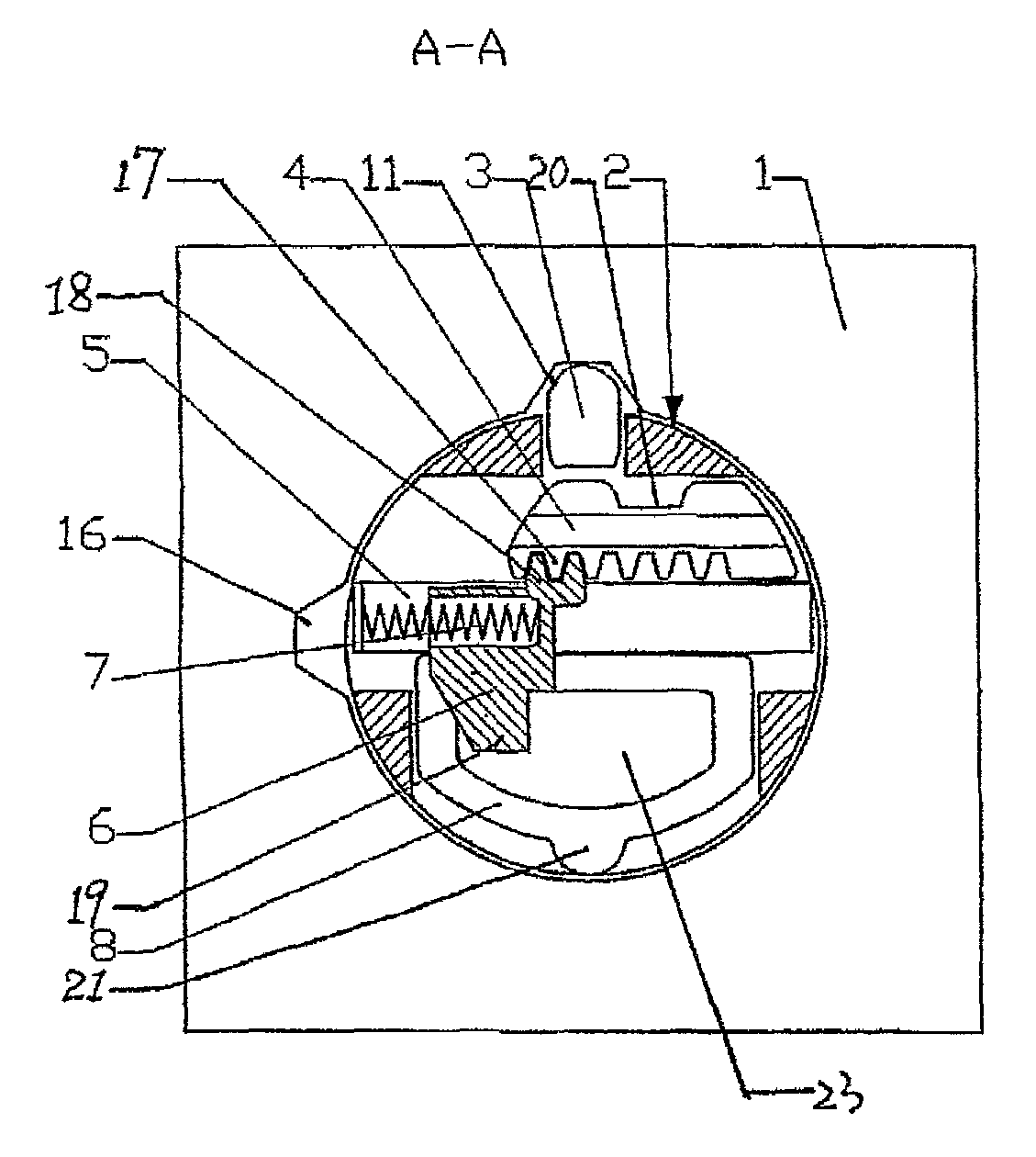
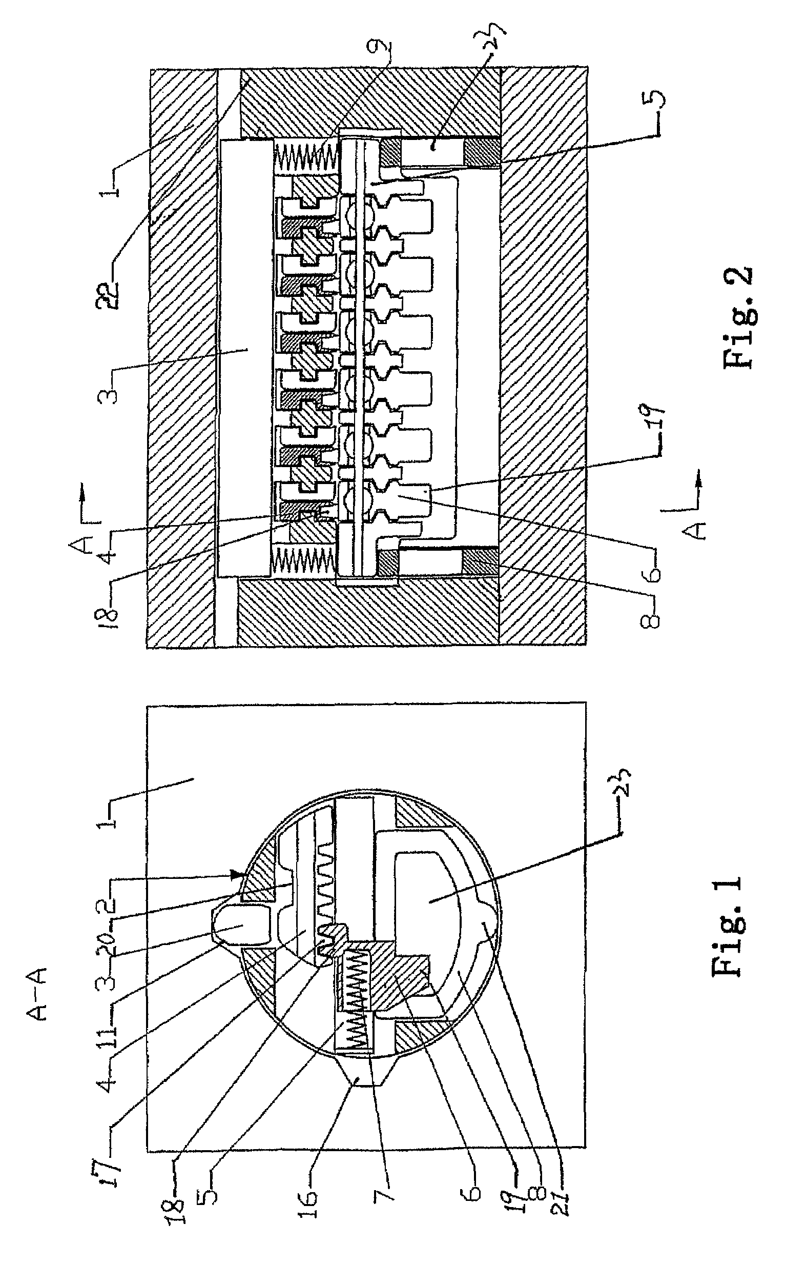
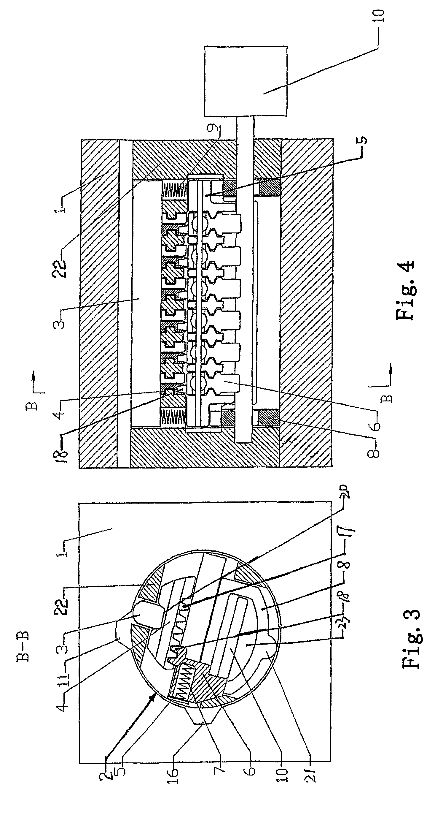
[0033]Now with reference to FIGS. 1 and 2, a multifunctional lock comprises a lock shell 1, and a lock core 2 provided inside the lock shell 1, wherein said lock core 2 includes a lock core body 22 rotatable with respect to said lock shell 1, a key bar 3 provided slidably on said lock core body 22, a support 5 for sliding blocks provided slidably on said lock core body 22, a plurality of toothed sliding blocks 6 provided slidably on the said support 5 for sliding blocks, and a plurality of tooth pieces 4 provided slidably with respect to said lock core body 22, a lock bar slot 11 to receive said lock bar 3 is opened on the said lock shell 1, each of said tooth pieces 4 is provided with a recess 20 on one side thereof and a plurality of upper teeth 17 extending downwards on the other side, each of said sliding blocks 6 is provided with lower teeth 18 extending upwards, a first elastic element 7 is provided between each of said sliding blocks 6 and its corresponding lock core body 22,...


PUM


Abstract

A multifunctional lock comprises a lock shell (1), a lock bar (3), movable tooth pieces (4), a support (5) for sliding blocks, sliding blocks (6) and a guide slot unit (8) for the insertion of a key. Wherein, an elastic element is provided between the lock bar and the support, the sliding blocks at least partially extend into the keyway of the unit. When the lock is unlocked, a projection of the unit has two operating positions, in one of which the projection is received into the cut of the shell and the upper teeth of the tooth pieces disengage from the bottom teeth of the sliding blocks, in another it is out of the cut and the upper teeth engage with the bottom teeth. The key of the lock can be changed many times.

Description

CROSS REFERENCE TO RELATED APPLICATIONS[0001]This application is a 35 U.S.C. 371 national phase application of International Application No. PCT / CN2006 / 001781, filed Jul. 20, 2006, which International Application was published by the International Bureau in Chinese on Mar. 15, 2007, and claims priority to Chinese Patent Application No. 200520075364.2, filed Sep. 9, 2005, and Chinese Patent Application No. 200620068971.0, filed Jan. 25, 2006, each of which is incorporated herein by reference in its entirety.TECHNICAL FIELD[0002]The present utility model relates to a multifunctional lock, and in particular, to a multifunctional lock which allows the key to be changed many times.BACKGROUND[0003]China Patent No. 200320123249.4 discloses a lock which allows the key to be changed, wherein the original key can be removed at any position of the rotation of the lock core and changed by a new key in the unlocked condition, thus causing a potential security hazard.SUMMARY OF THE INVENTION[0004...

Claims


Application Information

Patent Timeline
Patent Type & Authority Patents(United States)
IPC IPC(8): E05B29/06
CPCE05B29/0066E05B29/004Y10T70/7616Y10T70/7599Y10T70/7452Y10T70/752Y10T70/7734Y10T70/774E05B29/00E05B35/00
Inventor GAN, VINCENTSHEN, YANG
Owner MALAFON ELECTRONICS SUZHOU
Why Eureka
Try Eureka