
Robotic end of arm tool method and apparatus

Active Publication Date: 2009-11-03
SAS AUTOMATION
View PDF13 Cites 33 Cited by
  • Summary
  • Abstract
  • Description
  • Claims
  • Application Information

AI Technical Summary

Benefits of technology

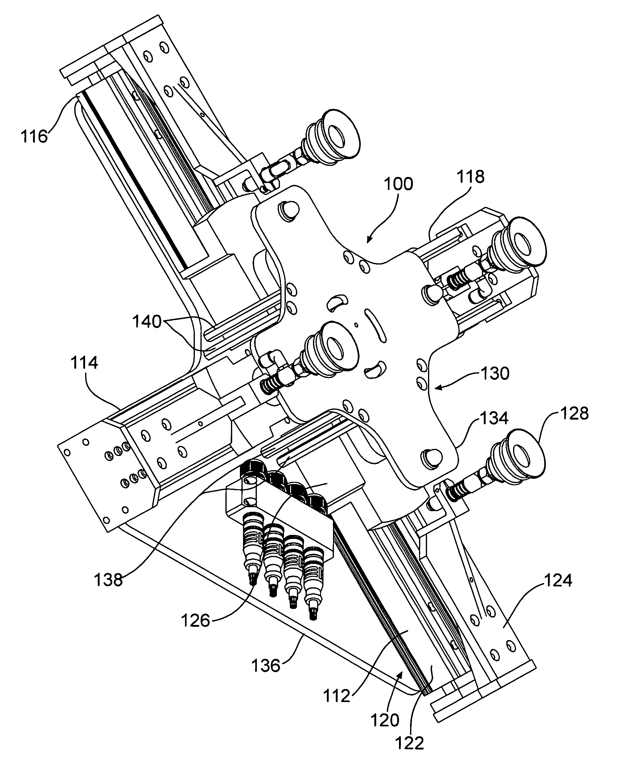
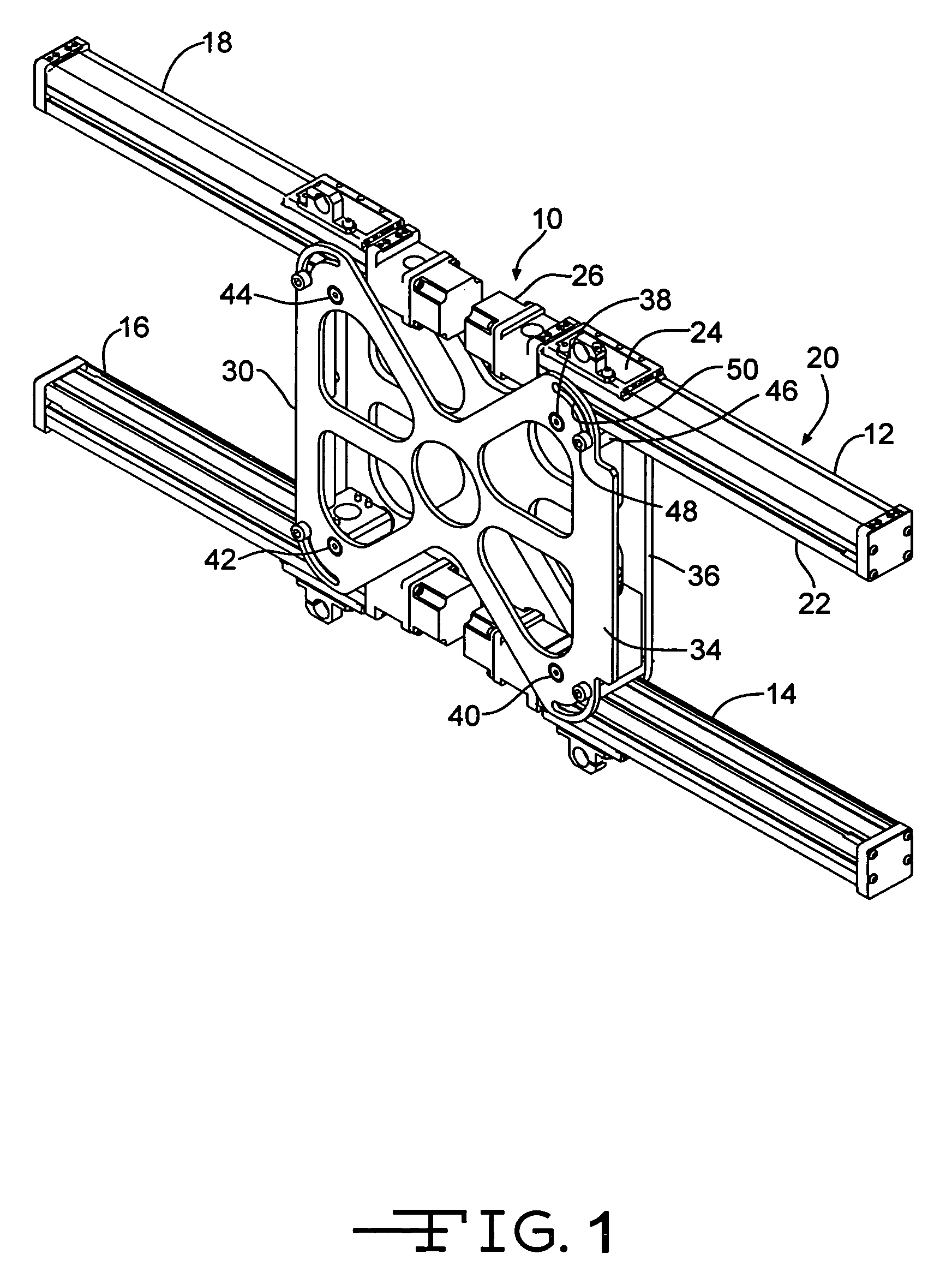
[0005]The invention may also include one form of an apparatus comprising an end of arm tool having a mounting bracket for mounting the end of arm tool on the robotic arm; a plurality of operating mechanisms mounted on the mounting bracket; and a plurality of gripping devices one each supported by a respective operating mechanism, each gripping device being independently movable by its respective operating mechanism along a separate elongated path spaced from the paths of the other gripping devices. Such an apparatus may also include each operating mechanism having at least one motor operatively connected to the respective gripping device for moving the respective gripping device along its respective path. Such an apparatus may further include each operating mechanism having a bracket movable by the at least one motor and the respective gripping device being secured to the bracket for movement with the bracket. Such an apparatus may yet further include at least one programmable controller for operating the motors so as to adjust the positions of the gripping devices along their respective paths to one of a plurality of predetermined positions established by the controller for gripping the article and to position the end of arm tool adjacent the article so that at least one of the gripping devices grips the article. Such an apparatus may also include each motor having a stepping mechanism controlled by at least one controller for positioning the respective gripping device at one of several predetermined locations. The apparatus may further include the elongated paths being linear and extending in a common plane. Yet further the apparatus may include the operating mechanisms being substantially identical and each independently pivotable in the common plane containing their elongated paths. The apparatus may also include a fastener associated with each operating mechanism for holding the operating mechanism in fixed position in the common plane after the operating mechanism has been pivoted.
[0006]The invention may include another form of an apparatus comprising an end of arm tool for attachment to a robotic arm, comprising a mounting bracket for mounting the end of arm tool on the robotic arm; a plurality of adjustable operating mechanisms mounted on the mounting bracket; a plurality of gripping devices one each associated with a respective operating mechanism and movable along a path to a desired location; and a plurality of motors at least one of which is operatively connected to a respective gripping device for moving that gripping device along that gripping device's respective path. Such an apparatus may also include each operating mechanism having a bracket movable by the respective motor and the respective gripping device being secured to the bracket for movement with the bracket. The apparatus may also i

Problems solved by technology

If this reconfiguration has to occur often, the cost of labor and the down time for utilization of the equipment can be significant.

Method used


Image

  • Robotic end of arm tool method and apparatus
  • Robotic end of arm tool method and apparatus
  • Robotic end of arm tool method and apparatus

Examples


Embodiment Construction

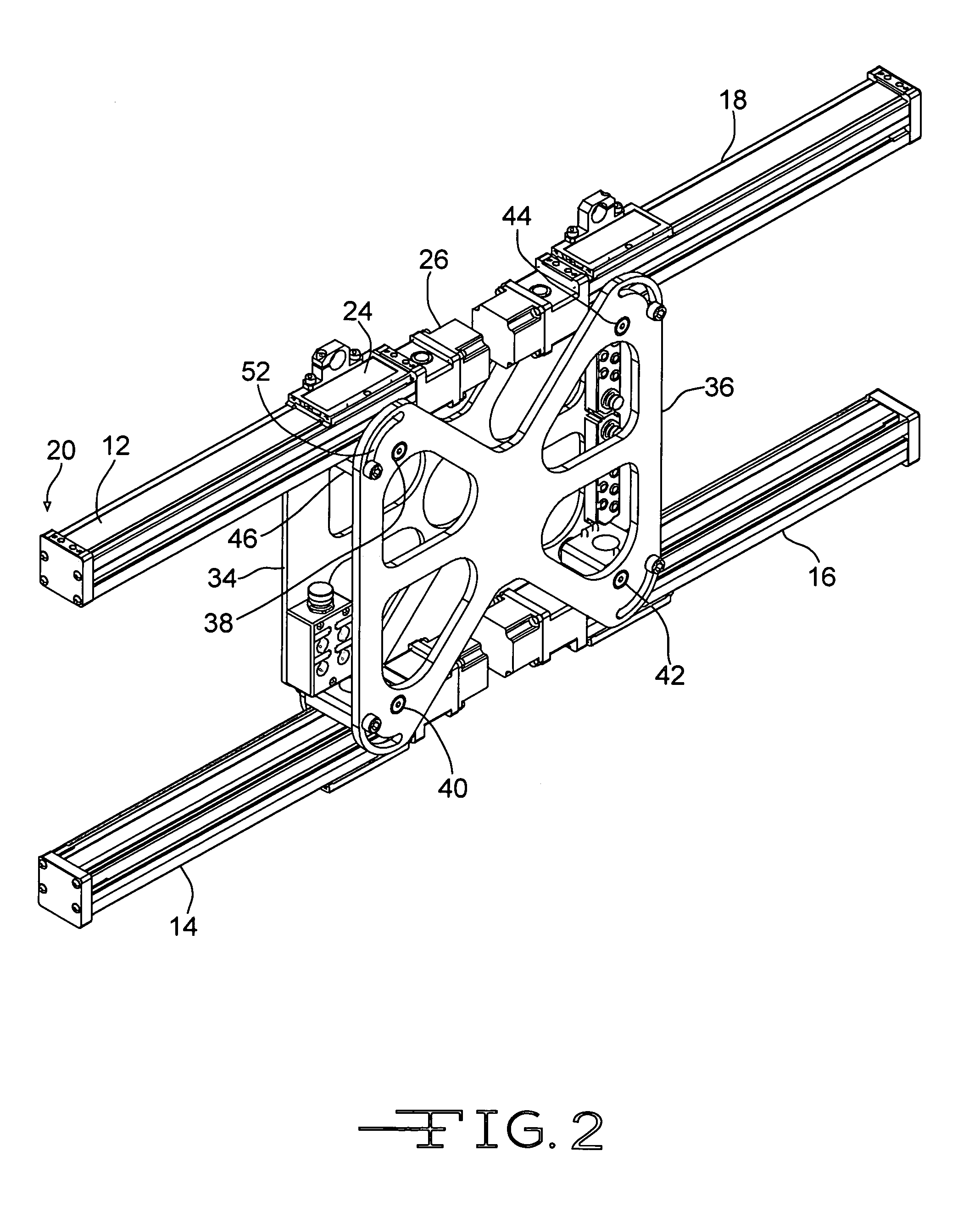
[0019]Referring now to the drawings, there is illustrated in FIG. 1 a first embodiment of the apparatus of the present invention generally designated by the numeral 10 which is an end of arm tool for a robot mechanism. Tool 10 includes four basic operating mechanisms 12, 14, 16 and 18, which are identical in construction. It is to be understood that more or fewer operating mechanisms may be used depending on the desired use. Taking operating mechanism 12 as an example, it includes a motor 20 which can be, for example, a slide table type stepping motor such as that designated as a series LXP from SMC Corporation, and which is illustrated in the figures of the first embodiment of the invention. This motor 20 basically includes a housing 22 and a bracket 24 supported by a lead screw (not shown) driven by a stepping motor 26. Bracket 24 can be moved longitudinally back and forth along housing 22 by rotation of the lead screw. It is to be understood that any one of a large number of othe...


PUM


Abstract

An end of arm tool has a mounting bracket mounting the end of arm tool to the robot arm for movement therewith and has a plurality of operating mechanisms mounted to the mounting bracket, a plurality of gripping devices each operatively connected to a respective operating mechanism and movable along a path, and a plurality of individual motors each operatively connected to a respective gripping device for moving the respective gripping device along its respective path. At least one programmable controller for operating the motors is provided to adjust the positions of the gripping devices along their respective paths to one of a plurality of predetermined positions established by the controller for gripping the article and to position the end of arm tool adjacent the article so that at least one of the gripping devices grips the article.

Description

BACKGROUND OF THE INVENTION[0001]This invention relates in general to robotic arms and end of arm tools for use in picking up and moving articles to or from a specific location.[0002]Robotic arms with end of arm tooling are used in many applications in many industries. Often these devices are controlled by a programmable controller to do a repetitive task with the end of arm tooling being manually set in a fixed position to repetitively pick up and release articles. If the robotic arm and end of arm tooling are to be used in a different situation, such as moving a different shape of article than the previous one, the end of arm tool usually has to be manually reconfigured for that purpose. If this reconfiguration has to occur often, the cost of labor and the down time for utilization of the equipment can be significant.SUMMARY OF THE INVENTION[0003]This invention relates to end of arm tooling for a robotic arm which together are programmable to change their configurations and operat...

Claims


Application Information

Patent Timeline
IPC IPC(8): B25J9/00B25J15/06
CPCB25J15/0052B25J15/0061B25J15/0616
Inventor FISHER, TRENT P.WESTBELD, JOHN MMILLER, ROBERT M.HEINZ, JASON R.
Owner SAS AUTOMATION
Learn More